
Fabrication of true apodized fiber Bragg grating using a new two-beam interferometer with polarization control

a two-beam interferometer and polarization control technology, applied in the field of exposure system and a two-beam interferometer for fabricating a true apodized fiber bragg grating, can solve the problems of unfavorable uniform refractive index, high price, undesired noise, etc., and achieve the effect of reducing time, cost and difficulty in fabrication

Inactive Publication Date: 2005-11-08
NAT CHIAO TUNG UNIV
View PDF7 Cites 3 Cited by
  • Summary
  • Abstract
  • Description
  • Claims
  • Application Information

AI Technical Summary

Benefits of technology

[0010]It is the primary object of the present invention to provide an exposure system and a method for fabricating a true apodized fiber Bragg grating, characterized in that only a single continuous exposure step is required to fulfill the variation of refractive index of any fiber Bragg grating, which effectively reduces the time, cost and difficulty in fabrication.

Problems solved by technology

As a matter of fact, these two prior art patents disclose methods that can not be immune from non-uniform refractive index and therefore the undesired noise.
Even though the phase mask is more convenient in use than the other prior art patents, it suffers from the high price.
In addition, due to the lack of flexibility in designing the variation of the refractive index of the grating, different phase masks are required when various fiber gratings are to be exposed.
However, the application of this method is limited due to standard design of the light-enhancement screen mask, which lacks of changeability in modulation of refractive index.
However, it requires an interferometer to precisely control the displacement of the fiber corresponding to the mask, which is very sensitive to the perturbation of the exposure system.
However, it is difficult to do so.

Method used


Image

  • Fabrication of true apodized fiber Bragg grating using a new two-beam interferometer with polarization control
  • Fabrication of true apodized fiber Bragg grating using a new two-beam interferometer with polarization control
  • Fabrication of true apodized fiber Bragg grating using a new two-beam interferometer with polarization control

Examples


Embodiment Construction

[0021]The present invention providing an exposure system and a method for fabricating a true apodized fiber Bragg grating can be exemplified by the preferred embodiments as described hereinafter.

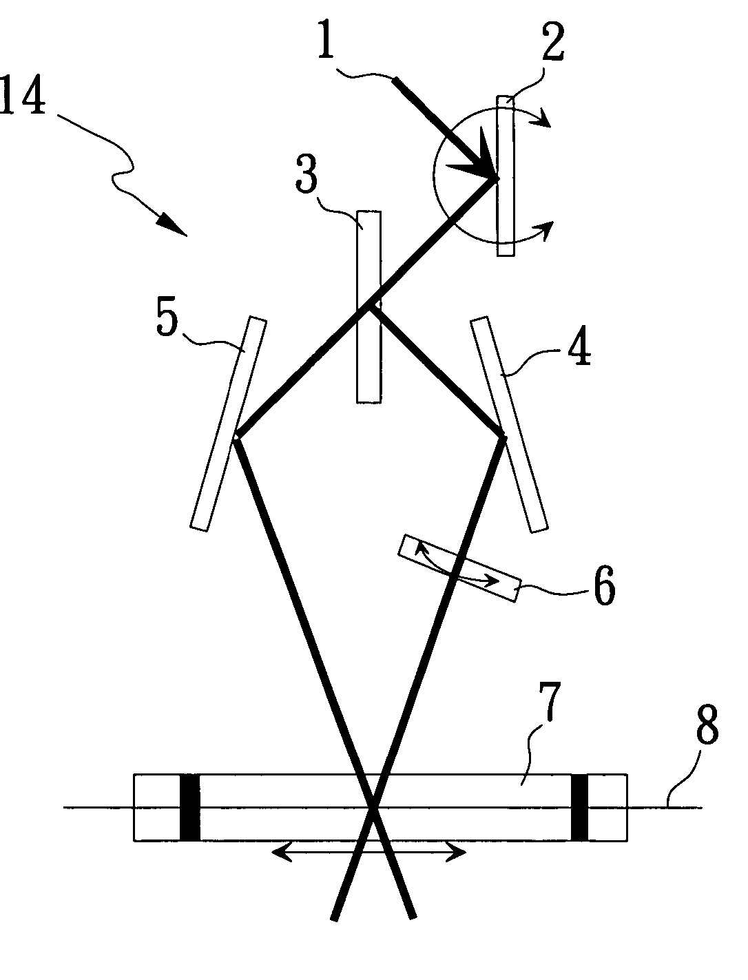
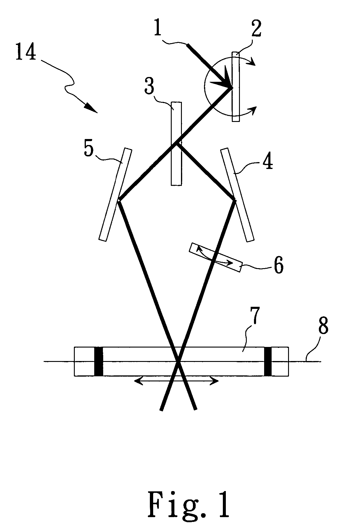
[0022]To start with, please refer to FIG. 1, which is a schematic diagram showing an exposure system 14 for the fiber grating in accordance with the present invention. The preferred embodiment of the present invention is shown as an exposure system 14 for forming a grating in a photosensitive fiber. The exposure system 14 comprises: a light source 1; a rotating reflection mirror 2; a beam splitter 3; a first fixed reflection mirror 4; a second fixed reflection mirror 5; a half-wave plate module 6; and a movable base 7.

[0023]The light source 1 generates a single-polarization light beam. In one embodiment of the present invention, the light source 1 is a UV light source for generating a UV light beam. The UV light beam passes through the rotating reflection mirror 2. Since the rotating reflect...


PUM

PropertyMeasurementUnit
photosensitiveaaaaaaaaaa
incident angleaaaaaaaaaa
refractive indexaaaaaaaaaa

Abstract

The present invention provides a two-beam interference exposure system that can be simply adjusted by rotating only one mirror. By placing a half-wave plate in one of the interference arms and precisely scanning the relative fiber position, the present invention can expose true apodized fiber Bragg gratings in a single scan by simultaneously rotating the angle of the half-wave plate. By rotationally switching the fast and slow axes of the half-wave plate, the present invention can also expose n-phase-shifted fiber grating by the same system.

Description

BACKGROUND OF THE INVENTION[0001]1. Field of the Invention[0002]The present invention generally relates to an exposure system and a method for fabricating a true apodized fiber Bragg grating and, more particularly, to an exposure system and a method for fabricating a true apodized fiber Bragg grating by using two-beam interferometer.[0003]2. Description of the Prior Art[0004]When fabricating a complex fiber Bragg structure, refractive-index modulation and phase control are the most concerned parameters. It is therefore important to uniform the dc refractive-index modulation in addition to phase control during the exposure scan.[0005]The Taiwan Patent Publication No. 436,667 discloses a method for fabricating a low-noise fiber Bragg grating by using a phase mask and an aperture so as to achieve uniform dc refractive-index modulation. Firstly in the method, a UV light passes through the aperture and then the phase mask as to form a grating in a photosensitive fiber. Secondly, the phas...

Claims


Application Information

Patent Timeline
Patent Type & Authority Patents(United States)
IPC IPC(8): C03C25/00G02B6/34G03H1/04G02B6/02
CPCG02B6/02133G02B6/02085G02B6/02152Y10S359/90
Inventor CHUANG, KAI-PINGSHEU, LIH-GENTSAI, MENG-CHANGLAI, YINCHIEH
Owner NAT CHIAO TUNG UNIV
Learn More