Method and apparatus for display image adjustment

Active Publication Date: 2005-11-08
NVIDIA CORP
View PDF2 Cites 39 Cited by
  • Summary
  • Abstract
  • Description
  • Claims
  • Application Information

AI Technical Summary

Benefits of technology

[0008]The present invention provides method and apparatus for adjusting an image, in particular a projected image. The image can be the desktop display of a computer, including that of various Microsoft Windows operating systems. Because it is not always feasible or desirable to have a projector perpendicular and centered to a screen, a graphic user interface (GUI) is provided to facilitate adjustment of the projected image when the projector is off-axis or not centered with respect to the screen. In essence, the GUI enables a user to move one or more corners or sides of the projected image in order to convert a pincushioned or trapezoidal projected image into a rectilinear projected image. Such adjustment by a user may be done in less than a minute. Additionally, an embodiment of the GUI enables the user to move the center of the projected image to adjust for anisotropy. An aspect of the present invention is a GUI for reducing distortion in a projected image. The GUI comprises handles projected with the projected image, where the handles are associated with vertices of the projected image and are selectable and moveable by a user for adjusting the projected image.
[0009]Another aspect of the present invention is a method for reducing distortion in a displayed image. Image content is obtained and stored as a texture having a set of texels. The image content is applied as a texture to at least one polygon having vertices associated with texture coordinates in the texture. The projected image is created by rendering the polygons with the image applied as a texture. The rendering can be done with a three-dementional (3D) graphics pipeline. In the GUI at least one handle related to a vertex of the vertices is displayed with the displayed image and moved to adjust the displayed image. Location of the at least one handle is updated in response to movement of the at least one handle. The vertex is changed in response to the location of the at least one handle update, texture coordinates of the set of texture coordinates are changed in response to the vertex change; and the displayed image is changed in response to change of the texture coordinates of the set of texture coordinates for adjustment of the displayed image.
[0011]Another aspect of the present invention is a method for counteracting distortion of a displayed image. Image content is obtained. Pixel values for the image content are written to an off-screen medium. Polygons using the image content written to the off-screen medium are rendered as a texture, and moveable vertices associated with the polygons are provided, where the vertices are associated with texture coordinates within the texture and are moveable for counteracting distortion of the displayed image.
[0012]Another aspect of the present invention is a GUI for reducing distortion in a displayed image. Objects are displayed with the displayed image. The objects are associated with vertices of the displayed image and are selectable and moveable by a user for adjusting the displayed image.

Problems solved by technology

However, these adjustments conventionally require using multiple adjustment modes, where an adjustment in one mode may affect another adjustment in another mode.
This leads to a time consuming iterative approach to bring a display image into alignment.
An additional annoyance is having a projector in the way of a presenter and attendees, as the projector conventionally is centered to the projected image to minimize distortion.
Furthermore, projecting an image off-axis to a screen or imaging surface can have effects other than keystoning, such as anisotropic or aspect ratio geometric distortion.

Method used


Image

  • Method and apparatus for display image adjustment
  • Method and apparatus for display image adjustment
  • Method and apparatus for display image adjustment

Examples


Embodiment Construction

[0040]In the following description, numerous specific details are set forth to provide a more thorough understanding of the present invention. However, it will be apparent to one of skill in the art that the present invention may be practiced without one or more of these specific details. In other instances, well-known features have not been described in order to avoid obscuring the present invention.

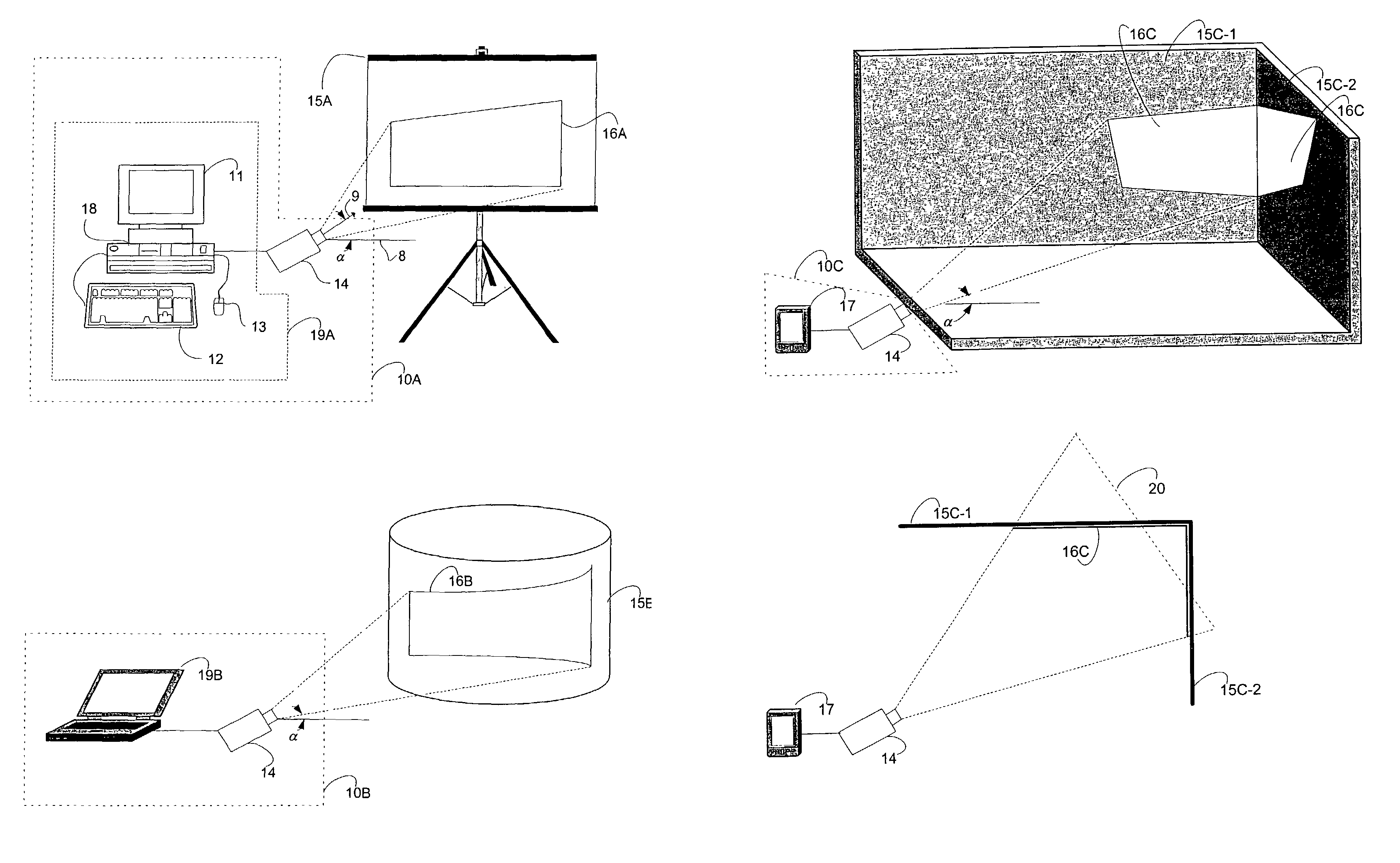
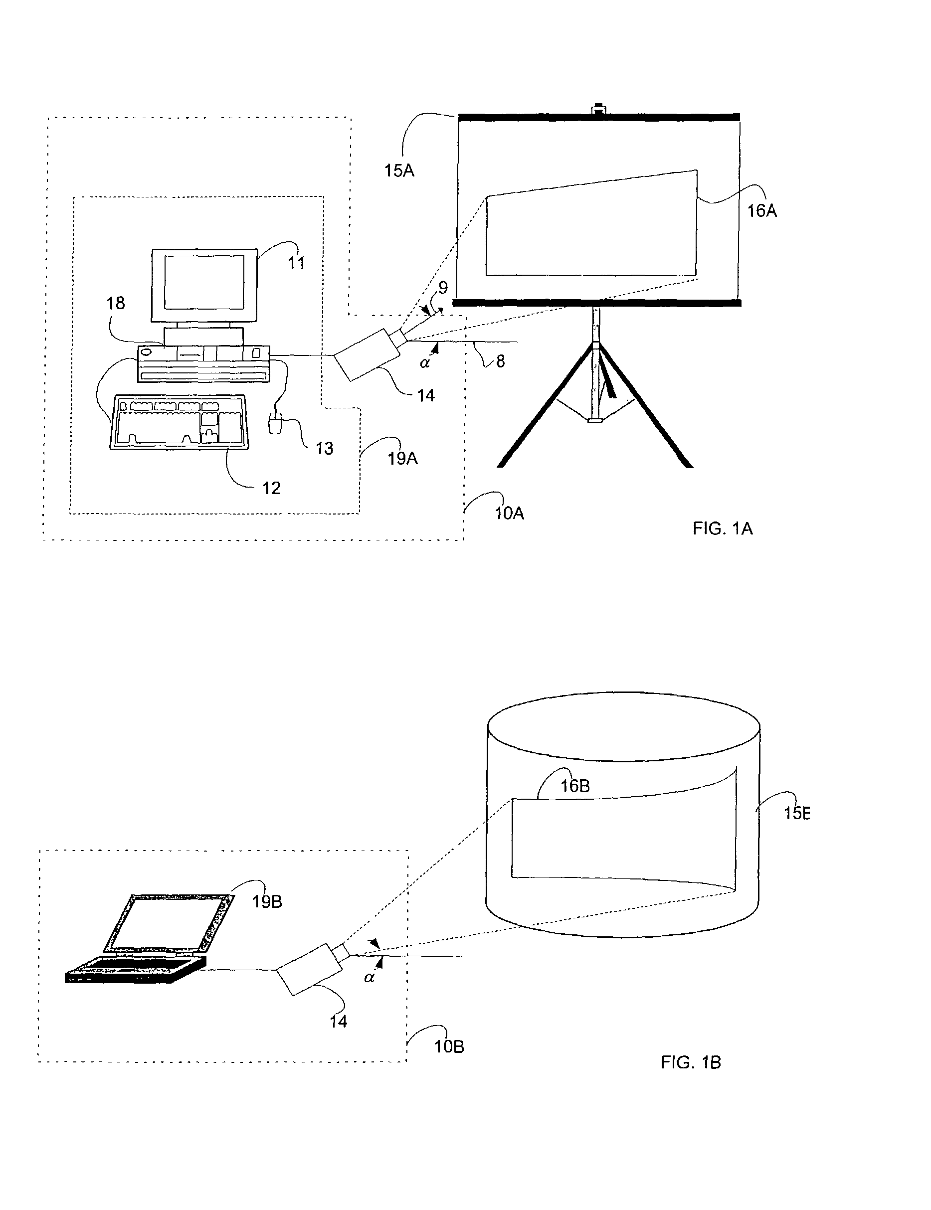
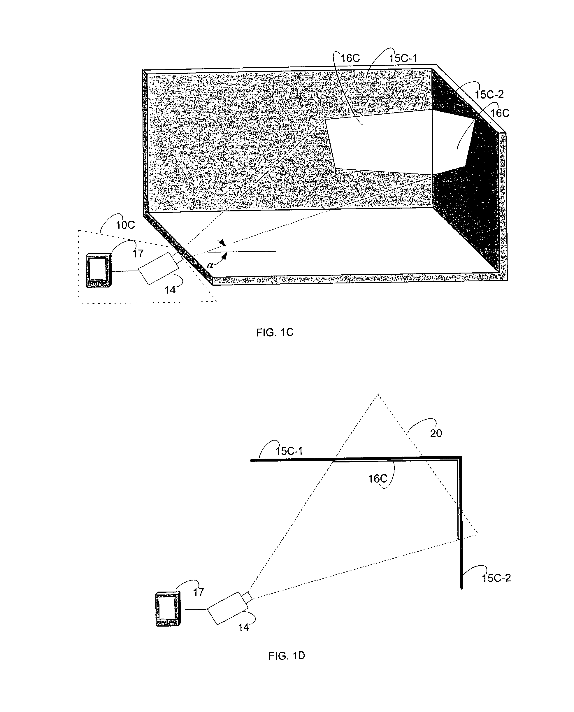
[0041]FIG. 1A is a pictorial view of an exemplary embodiment of an image projection system 10A in accordance with one or more aspects of the present invention. Image projection system 10A comprises computer system 19A and projector 14. Computer system 19A comprises computer monitor 11, mouse 13, keyboard 12 and computer 18. Computer 18 comprises an image adjustment program, described below in more detail. An image stored in computer 18, or obtained from a network when computer 18 is coupled to such a network, is provided as output to projector 14. Projector 14 projects such an image ont...


PUM


Abstract

Method and apparatus for display image adjustment is described. More particularly, handles associated with polygon vertices of a polygon rendered image are provided as a graphical user interface (GUI). These handles may be selected and moved by a user with a cursor pointing device to adjust a displayed image for keystoning, among other types of distortion. This GUI allows a user to adjust a projected image for position of a projector with respect to imaging surface, as well as for imaging surface contour, where such contour may be at least substantially planar, cylindrical, or spherical and where such contour may comprise multiple imaging surfaces. This advantageously may be done without special optics or special equipment. An original image is used as texture for rendering polygons, where the image is applied to the rendered polygons.

Description

CROSS-REFERENCE TO RELATED APPLICATIONS[0001]This application claims benefit of U.S. Provisional Patent Application Ser. No. 60 / 384,663, entitled “Method and Apparatus for Display Image Adjustment,” filed May 31, 2002 which is herein incorporated by reference.FIELD OF THE INVENTION[0002]The present invention relates generally to method and apparatus for display image adjustment, and more particularly to method and apparatus for screen display or projected image adjustment to adjust for geometric distortion.BACKGROUND OF THE INVENTION[0003]Anyone who has ever viewed an image on a television set, a computer monitor, a projection screen or other projection surface, and the like, where one corner of the image was out of alignment has experienced a form distortion, namely, a geometric distortion called “keystoning” or “keystone” geometric distortion. Keystoning is where an image is out of alignment, conventionally at one or more of the corners, of the image producing a trapezoidal or tra...

Claims


Application Information

Patent Timeline
IPC IPC(8): G09G5/00H04N9/31
CPCH04N9/31H04N9/3185
Inventor DIAMOND, MICHAEL B.MOREY, DAVID R.DE WAAL, ABRAHAM B.
Owner NVIDIA CORP
Why Eureka
Try Eureka