
Apparatus for sensing current

a current sensor and applicator technology, applied in the field of sensing power line current, can solve the problems of unnecessarily cutting off power, and the cost of adding a new current sensor to the product can be very expensiv

Inactive Publication Date: 2005-11-08
ABB SPA
View PDF5 Cites 97 Cited by
  • Summary
  • Abstract
  • Description
  • Claims
  • Application Information

AI Technical Summary

Problems solved by technology

The accuracy of such current sensors is important, since inaccurate current sensing could lead to unnecessarily cutting-off power to a load and discrepancies and inaccuracies in power metering, which are undesirable.
For example, if products must be redesigned in order to incorporate a new current sensor, the cost of adding the new current sensor to the product can be very expensive.

Method used


Image

  • Apparatus for sensing current
  • Apparatus for sensing current
  • Apparatus for sensing current

Examples


Embodiment Construction

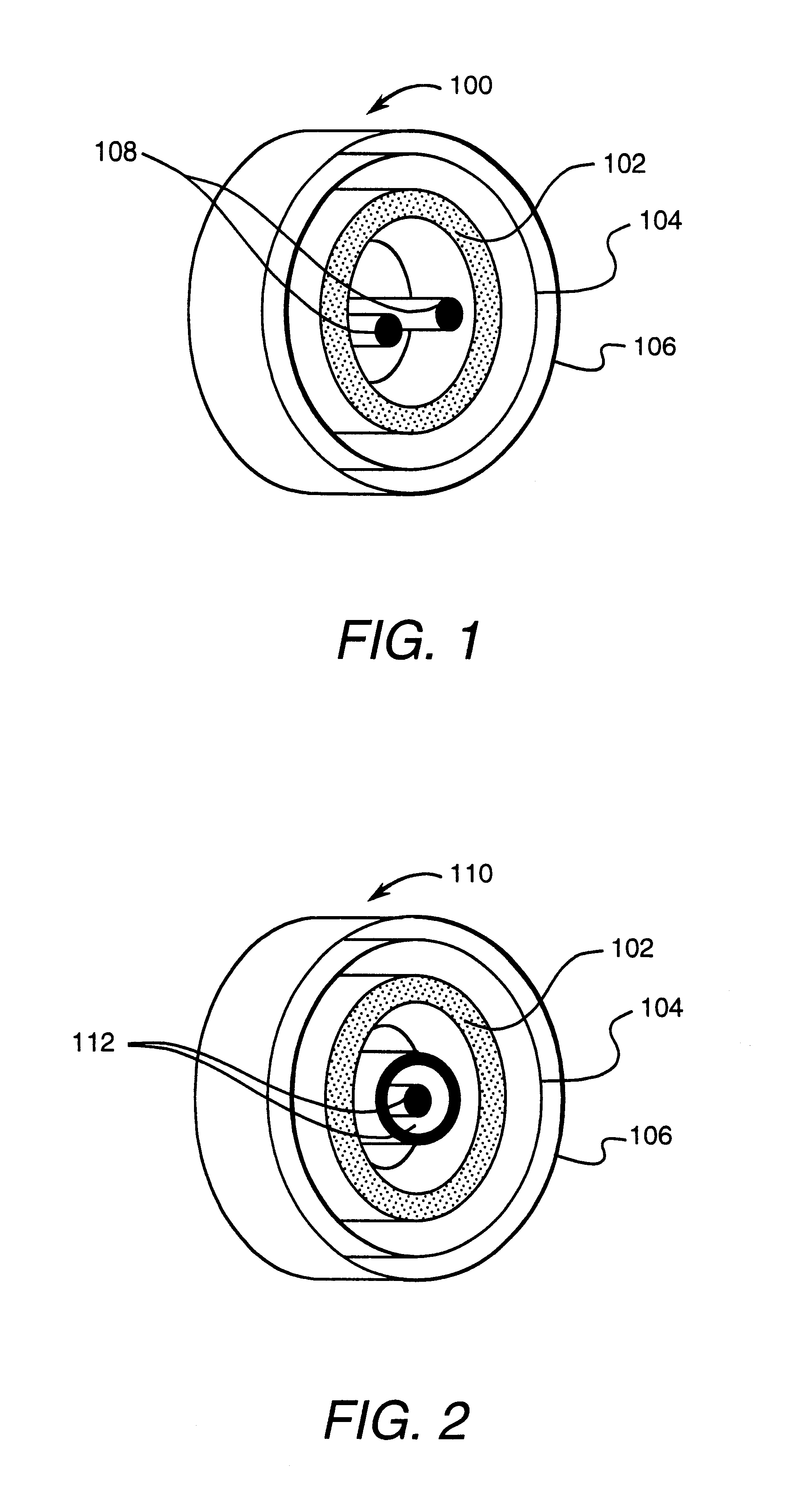
[0035]FIG. 1 illustrates an asymmetric sensor assembly 100 which includes a sensor 102, a housing 104 positioned around sensor 102, and a magnetic shield 106 positioned around housing 104. Sensor 102, housing 104, and magnetic shield 106 are of toroidal symmetry and arranged coaxially about a pair of asymmetric primary current conductors 108. Conductors 108 are disposed side-by-side such that the center of the line joining the centers of the conductors is at the geometric center of the remaining toroidal assembly. This relative position is registered by use of simple attachments or a registration part (not shown in FIG. 1 for clarity), that maintain the appropriate relative positional relationships of sensor assembly 100.

[0036]FIG. 2 illustrates another embodiment of a symmetric sensor assembly 110 which includes sensor 102, housing 104 positioned around sensor 102, and magnetic shield 106 positioned around housing 104. Sensor 102, housing 104, and magnetic shield 106 are of toroida...


PUM


Abstract

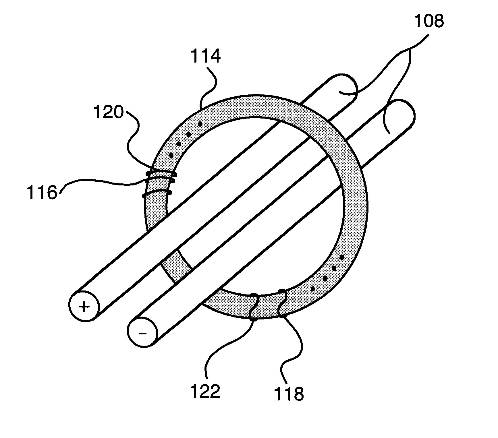
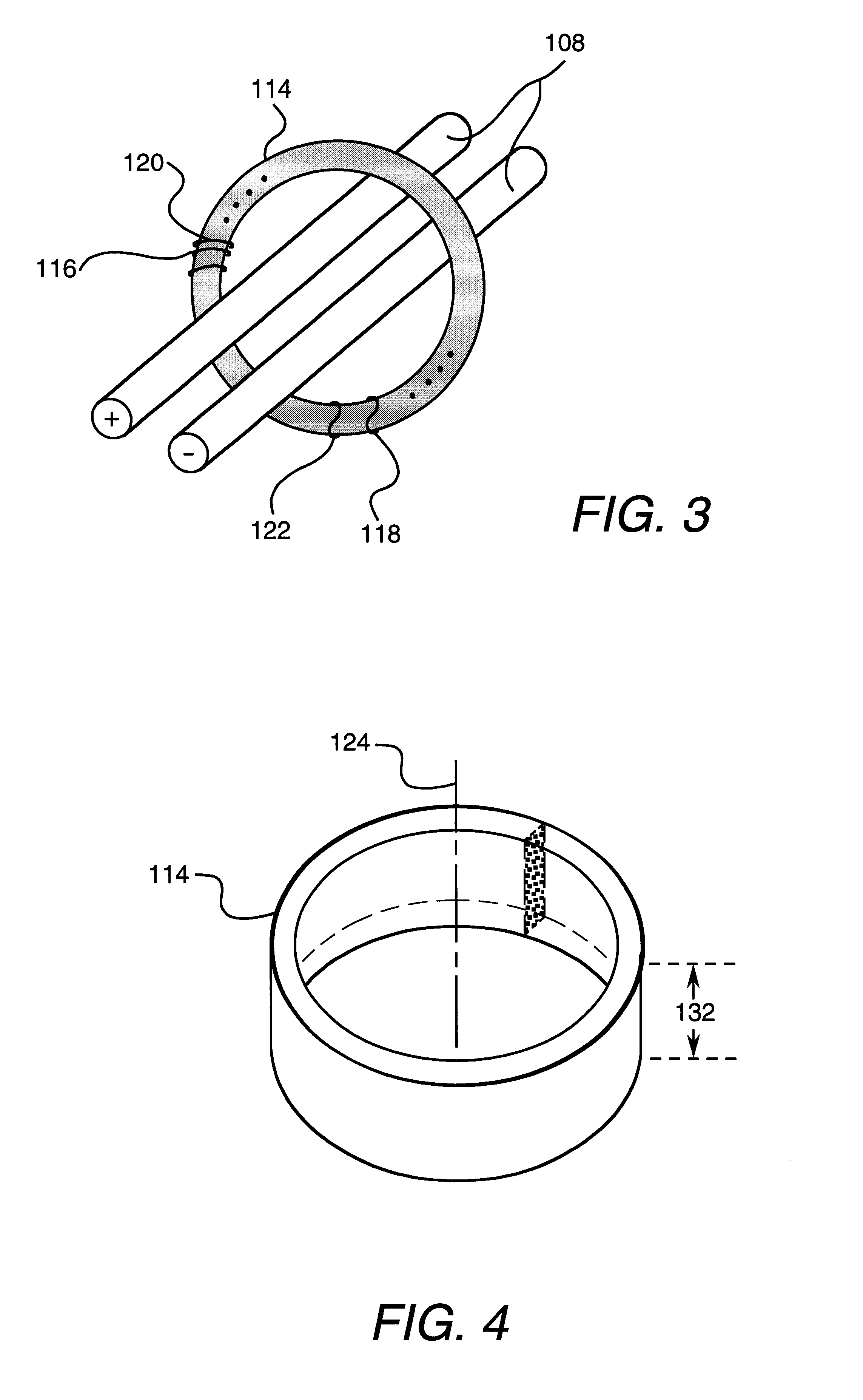
A current sensor assembly includes a sensor coil, an electrostatic shield coil, a core, a housing, and a magnetic shield. The sensing coil, electrostatic shield coil, core, housing, and magnetic shield can be of toroidal symmetry and arranged coaxially about a pair of primary current conductors. The conductors can be either asymmetric or symmetric with respect to the geometric center of the remaining sensor assembly. The core and a secondary winding make up a current sensor. The core is cylindrically shaped and fabricated of non-magnetic material. The secondary winding is wound over the cylindrical core to form a toroidally shaped winding. When assembled into the current sensor assembly, the core and windings are disposed around two single turn primary windings through which AC currents to be measured flow. Alternatively, the conductor can be flat and the sensor can be a solid state sensor that includes an electrostatic shield. The conductor can have a magnetic flux concentrator positioned about the conductor in the same region where the sensor is located.

Description

CROSS REFERENCE TO RELATED APPLICATION[0001]This application is a division of application Ser. No. 09 / 133,646 filed Aug. 13, 1998 which is hereby incorporated by reference in its entirety.[0002]This Application claims the benefit of U.S. Provisional Application No. 60 / 055,903, filed Aug. 15, 1997.FIELD OF THE INVENTION[0003]This invention relates generally to sensing power line current and, more particularly, to a current sensor responsive to magnetic fields.BACKGROUND OF THE INVENTION[0004]Power distribution systems include many electrical devices. Some of the electrical devices have current sensors for sensing current flow in a conductor. For example, power distribution systems generally include circuit breakers, electricity meters, and monitoring equipment. The accuracy of such current sensors is important, since inaccurate current sensing could lead to unnecessarily cutting-off power to a load and discrepancies and inaccuracies in power metering, which are undesirable. Although ...

Claims


Application Information

Patent Timeline
Patent Type & Authority Patents(United States)
IPC IPC(8): G01R33/00G01R1/18G01R15/18
CPCG01R15/183G01R1/18G01R15/181
Inventor BERKCAN, ERTUGRUL
Owner ABB SPA
Learn More