
Control apparatus for an illuminating device

a technology of control apparatus and illuminating device, which is applied in the direction of lighting and heating apparatus, electric variable regulation, instruments, etc., can solve the problem of almost impossible to distinguish between electronic light and natural candle light, and achieve the effect of avoiding driving or controlling and saving electrical energy

Inactive Publication Date: 2005-11-08
SUCKFULL GERHARD +2
View PDF2 Cites 9 Cited by
  • Summary
  • Abstract
  • Description
  • Claims
  • Application Information

AI Technical Summary

Benefits of technology

"The present invention relates to a control apparatus for electronic candles and other illuminating devices that can create a natural flickering effect. The control apparatus has a microprocessor circuit that produces an output signal with either no periodicity or a periodicity so long that the viewer cannot recognize it. This creates a flickering effect that is similar to a natural candle flickering in the wind. The control apparatus can be used in various forms such as table candles, hurricane lamps, or grave lights. The apparatus can be controlled by a program that includes a repeating loop in which a register of the microprocessor takes on different values, and the difference value is used to control the time period for which the illuminating device is switched on. The control apparatus can also be used with multiple output terminals for controlling multiple illuminating devices. The apparatus can generate a non-periodic impression on the viewer by using a random number generator. The control apparatus can also be used in environments where it is very bright or in the absence of a flame. The invention provides a control apparatus that can create a natural flickering effect and can be used in various forms."

Problems solved by technology

For the viewer the impression of a natural flickering in the wind is thereby achieved, so that it is almost impossible to distinguish between the electronic light and natural candle light.

Method used


Image

  • Control apparatus for an illuminating device
  • Control apparatus for an illuminating device
  • Control apparatus for an illuminating device

Examples


Embodiment Construction

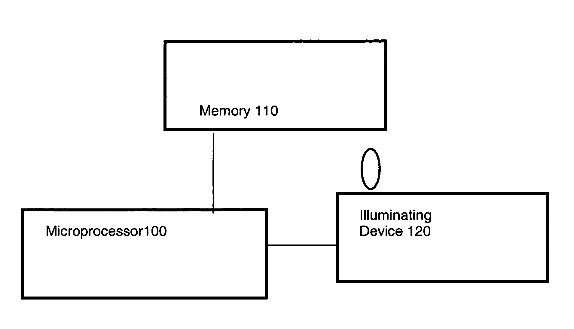
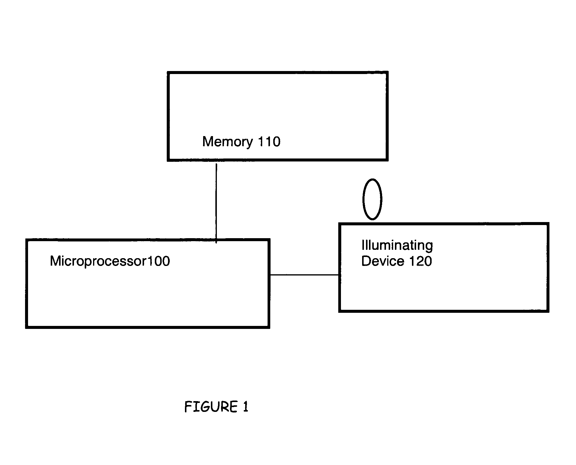
[0028]FIG. 1 schematically illustrates a circuit according to an embodiment of the invention. The microprocessor 100 is operated according to a program which is stored in memory 110. Based on this program and by means of an output terminal 115 of microprocessor 100 an illuminating device 120 is driven and controlled. The illuminating device may for example be a light emitting diode LED, an electric bulb, a halogen lamp, or the like. The microprocessor outputs a control signal to its output terminal 115 which either takes the value “1” or “0”.

[0029]Depending there-upon the illuminating apparatus 120, which may comprise further an additional power supply circuit, is switched on and off.

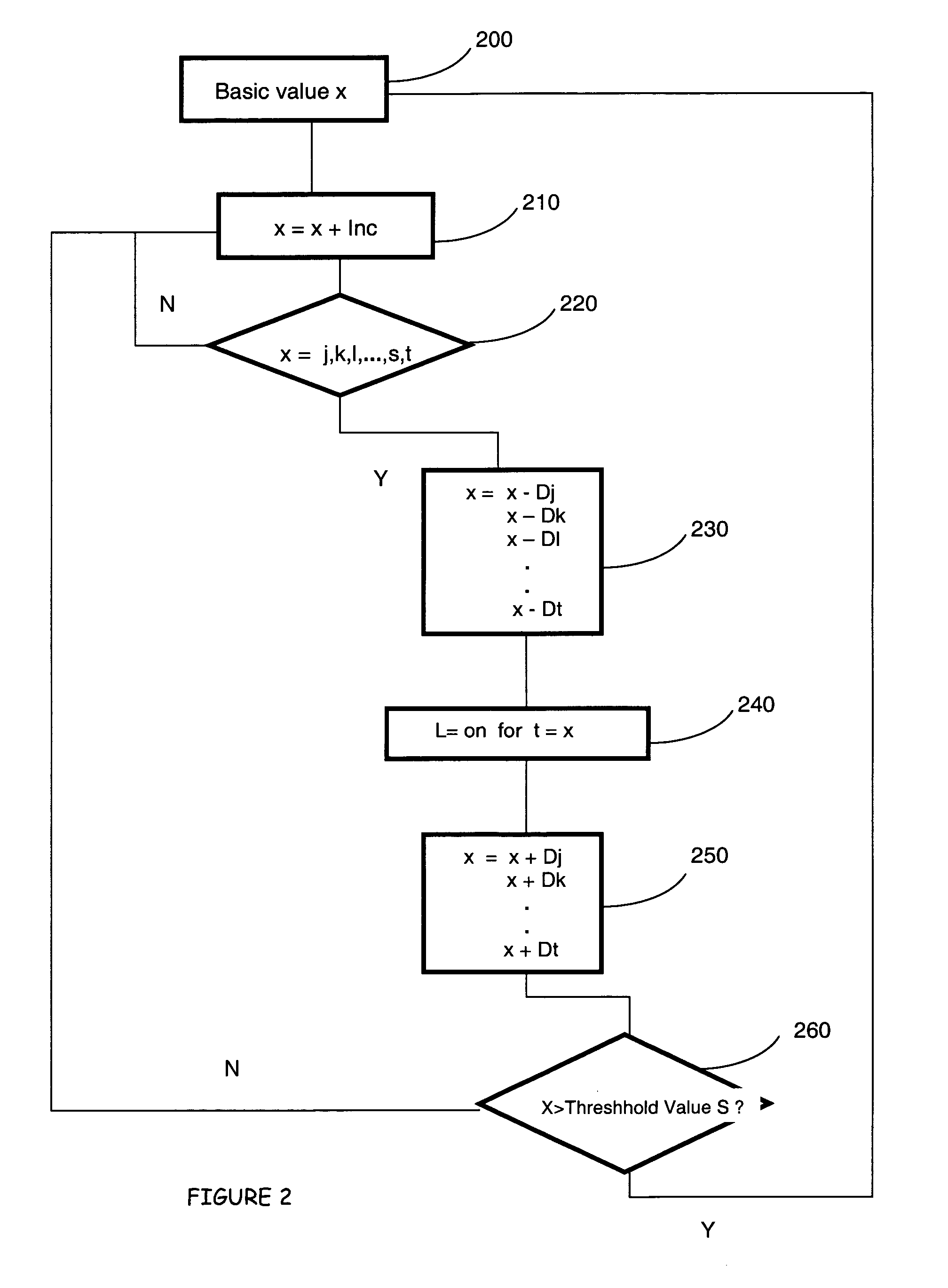
[0030]The control procedure itself now will be described with respect to FIG. 2. FIG. 2 schematically illustrates a flowchart of a program which can be used for controlling illuminating device 120.

[0031]The program in principle is designed as a loop. Starting from a basic value X (operation 200) this va...


PUM


Abstract

The invention relates to a control apparatus for controlling one or more lamps or illuminating means, so then the control apparatus comprises a microprocessor circuit which is adapted to output an output signal for controlling or driving the one or more lamps or illumination means, whereas the controlling signal is either completely non-periodic or has a period duration which is so long that the signal cannot be perceived by the human viewer as periodic.

Description

CROSS REFERENCE TO RELATED APPLICATION[0001]This application claims priority from European Patent Application No. EP 03009253.0 filed Apr. 23, 2003, and entiled “Control Apparatus for an Illuminating Device”.FIELD OF THE INVENTION[0002]The present invention relates to a control apparatus for controlling one or more lamps or lights or illuminating devices.BACKGROUND ART[0003]Control apparatuses for lamps or illuminating devices are known since a long time, whereas depending on the environmental conditions and the desired results, quite different control apparatuses or control devices may be used. The used devices ranged from a simple switch with which a lamp can be switched on and off up to a relatively complex control apparatus, for example for colouring organs in discos or theatres or the like, where depending on parameters from the outside a control of the lamps or lights is executed.[0004]Based on this prior art it is an object of the present invention to provide a control appara...

Claims


Application Information

Patent Timeline
Patent Type & Authority Patents(United States)
IPC IPC(8): H05B39/09H05B37/02H05B39/00F21V23/04F21S10/04F21S10/00F21S4/00
CPCH05B37/0281H05B37/029H05B39/09F21S6/001F21S10/04F21V23/0407Y02B20/42H05B47/16H05B47/155Y02B20/40
Inventor ROSE, MICHAEL
Owner SUCKFULL GERHARD
Learn More