
Transmission, particularly automatic transmission, with several shifting elements

a technology of transmission and shifting elements, applied in the field of transmission, can solve the problems of occupying a lot of structural space and being very costly, and achieve the effects of less structural space, less manufacturing cost and reduced drag loss

Inactive Publication Date: 2005-11-08
ZF FRIEDRICHSHAFEN AG
View PDF18 Cites 32 Cited by
  • Summary
  • Abstract
  • Description
  • Claims
  • Application Information

AI Technical Summary

Benefits of technology

[0006]According to the invention, by virtue of the fact that the shift control elements in the transmission that are engaged when shifting up a gear are formed as frictional shift control elements, and the shift control elements which, when shifting up, each constitute only a shift control element to be disengaged, are each made as form-locking shift control elements. A transmission is provided in this case which, compared with the transmissions known from the prior art, takes up less structural space and can be manufactured less expensively, since the transmission has fewer friction elements and pressure regulators.
[0008]Advantageously, according to the invention, the use of a transmission in a vehicle in which frictional shift control elements are replaced by positive-locking shift control elements, results in improved acceleration since the positive-locking elements are more compact and lighter.
[0010]A further advantage resulting from the positive-locking shift control elements is that in general higher drive torques can be transmitted by positive-locking than by frictional shift control elements without having to apply a high holding or closing pressure for the positive-locking shift control elements by means of a hydraulic system.

Problems solved by technology

Such automatic transmissions, however, have the disadvantage that all the shift control elements are in the form of multiple-disc couplings or brakes, which take up a lot of structural space and are very costly.

Method used


Image

  • Transmission, particularly automatic transmission, with several shifting elements
  • Transmission, particularly automatic transmission, with several shifting elements
  • Transmission, particularly automatic transmission, with several shifting elements

Examples


Embodiment Construction

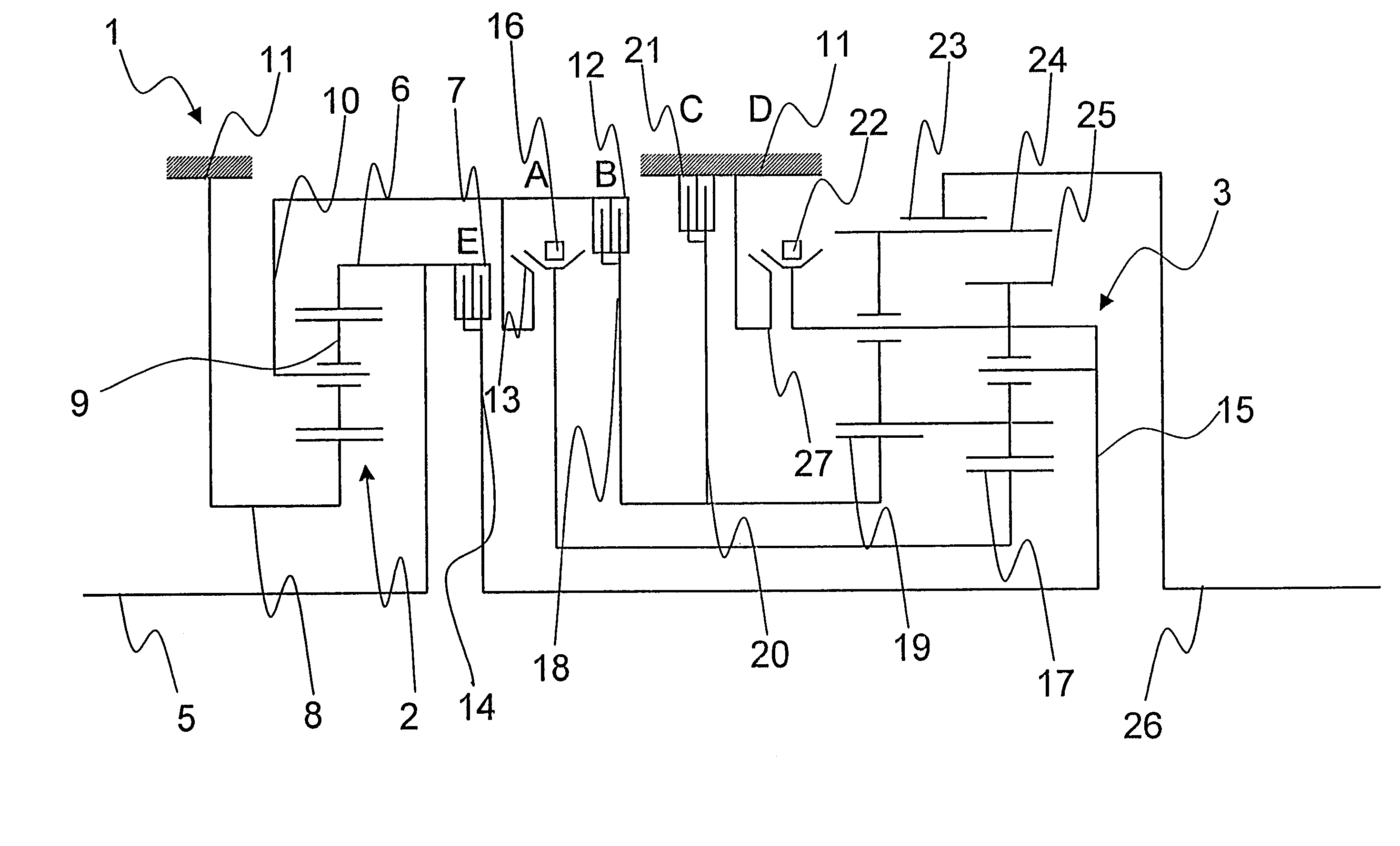
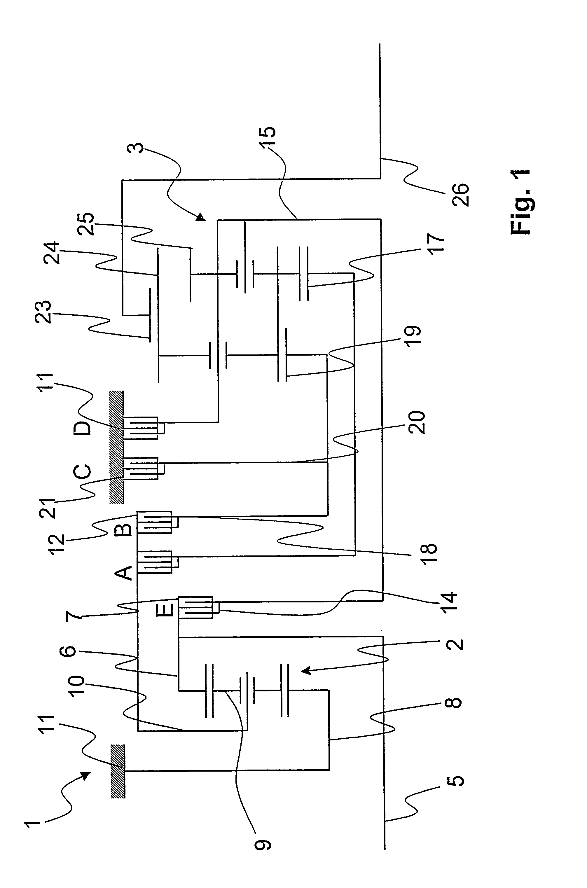
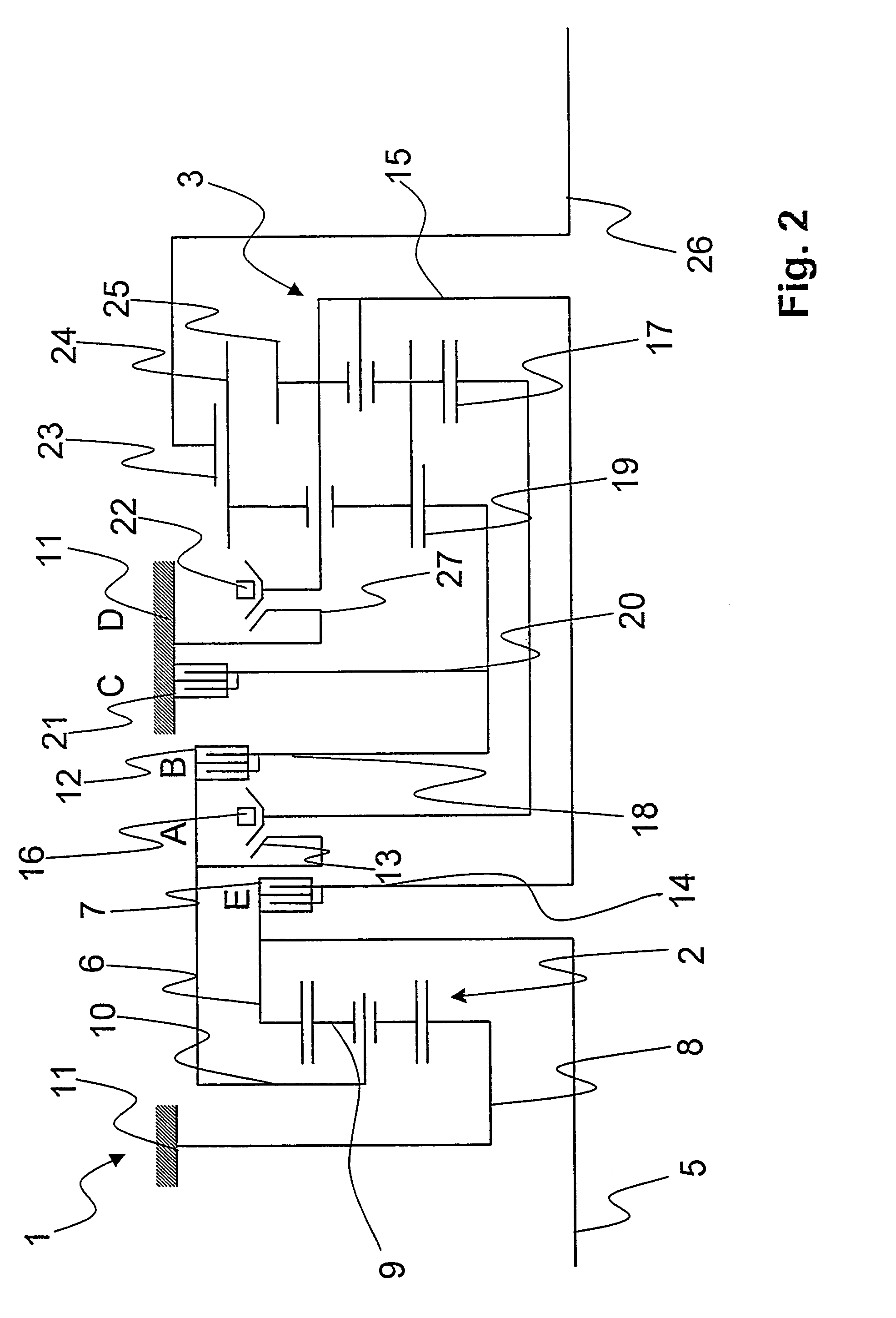
[0017]Referring to FIGS. 1 and 2, in each case a schematic gearwheel arrangement 1 of an automatic or planetary transmission, respectively, is shown, which has on the transmission input side a first planetary gearwheel assembly 2 and on the transmission output side a second planetary gearwheel assembly 3.

[0018]The second planetary gearwheel assembly 3 is made as a dual planetary gearwheel assembly and constitutes a so-termed Ravigneaux assembly. Between the two planetary gearwheel assemblies 2, 3 are five shift control elements designated A, B, C, D and E and, in each case, two of these shift control elements must be closed to establish a transmission ratio of the planetary transmission.

[0019]The schematic gearwheel arrangement of FIG. 1 corresponds essentially to that of FIG. 2, but all the shift control elements A to E of the arrangement 1 in FIG. 1 are made as frictional shift control elements. In the gearwheel arrangement 1 of FIG. 2, shift control elements A and D are positive-...


PUM


Abstract

A transmission is described, in particular an automatic transmission, which has several shift control elements (A, B, C, D, E) and several gearwheels (2, 3) which can be engaged via the shift control elements (A to E) to form a power flow, in which, to establish a transmission ratio in each case at least one of the shift control elements (A to E) is closed. The shift control elements (B, C, E), which are engaged during an up-shift, are formed as frictional shift control elements, and the shift control elements (A, D), which during up-shifts respectively only constitute a shift control element to be disengaged, are made as positive-locking gear elements.

Description

FIELD OF THE INVENTON[0001]The invention concerns a transmission, in particular an automatic transmission.BACKGROUND OF THE INVENTION[0002]From DE 199 10 299 C1 a planetary gear shift mechanism is known, in which an input shaft can be brought into driving engagement with an output shaft by at least one of three planetary gear divided transmissions. Using three respective friction couplings and brakes, five forward gears including one with transmission ratio 1 corresponding to direct throughput can be engaged. By interrupting a particular drive connection between two of the three divided transmissions an additional, sixth forward gear can be obtained. Alternatively, the additional sixth forward gear can be obtained by means of additional auxiliary planetary elements and an additional, outer auxiliary central gearwheel which meshes with the latter, such that the auxiliary central gearwheel can be braked by an additional brake in the sixth forward gear. In a different embodiment this a...

Claims


Application Information

Patent Timeline
Patent Type & Authority Patents(United States)
IPC IPC(8): F16H3/08F16H3/66F16H3/091F16H3/44
CPCF16H3/0915F16H3/663F16H2200/0052F16H2200/0056Y10T74/19223F16H2200/2007F16H2200/2023F16H2200/2097F16H2200/0091
Inventor DREIBHOLZ, RALFGUMPOLTSBERGER, GERHARDEBENHOCH, MICHAEL
Owner ZF FRIEDRICHSHAFEN AG
Learn More