
Method and apparatus for object recognition

a technology of object recognition and object detection, applied in the field of object recognition methods and methods, can solve the problems of difficult detection of human accurately, complex structure of image capture system, and difficulty in detecting human accurately, etc., and achieves the effect of improving the reliability of target object recognition, high level of recognition reliability, and convenient provision

Inactive Publication Date: 2005-11-01
PANASONIC CORP
View PDF4 Cites 113 Cited by
  • Summary
  • Abstract
  • Description
  • Claims
  • Application Information

AI Technical Summary

Benefits of technology

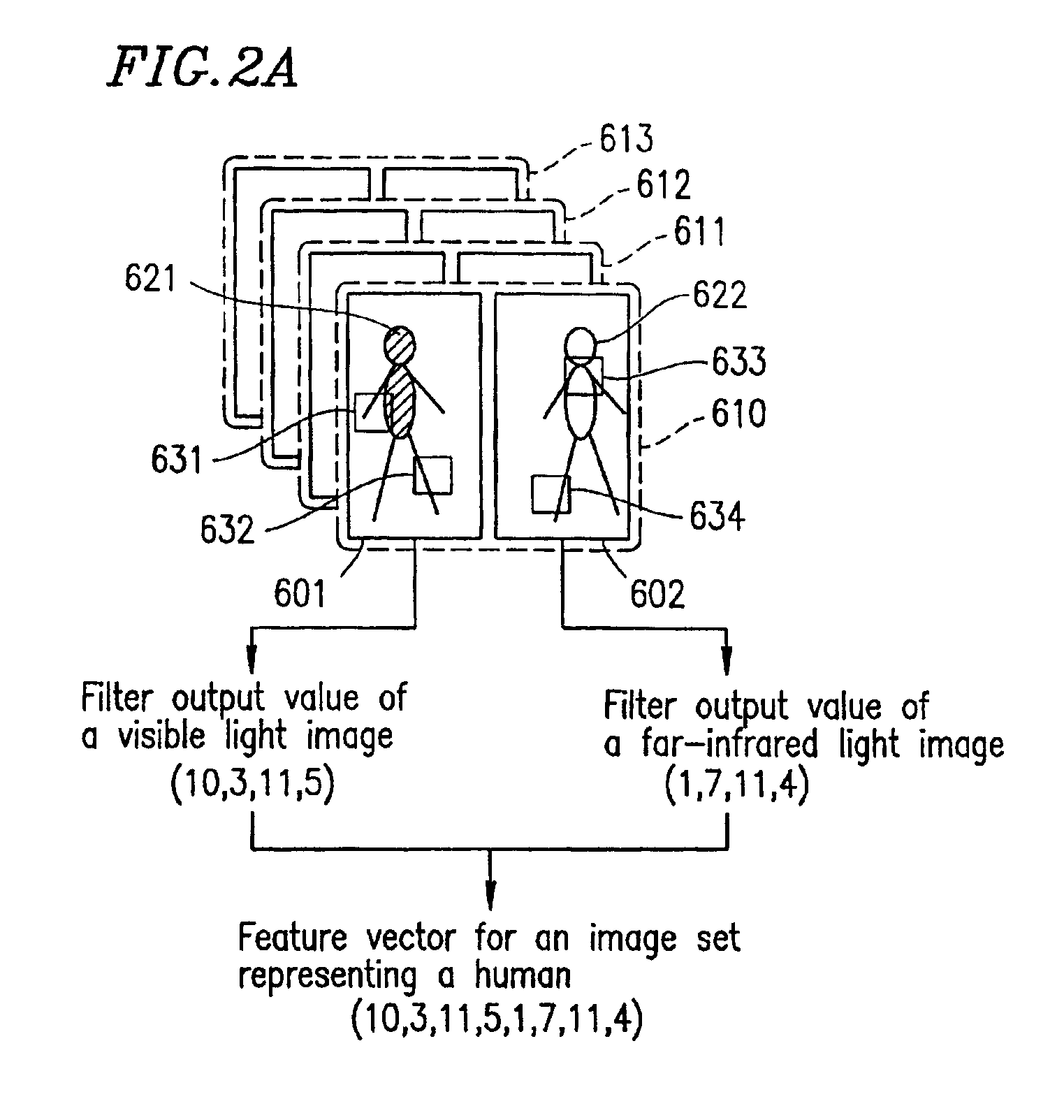
[0026]According to the present invention, an input image set to be recognized (first image set) includes a first image representing a target object (first target object) using a first attribute, and a second image representing the target object using a second attribute different from the first attribute. Whether or not the target object is categorized into a specific category is judged based on the first and second attributes, thereby improving the reliability of the recognition of the target object. Further, a predetermined image filter is applied to a predetermined position of a predetermined number of images to obtain a feature, which is used as a component to obtain a feature vector in a feature space. The image set is thus represented by the feature vector. Such a process does not require the matching of a region of the first image and a region of the second image, whereby it is not difficult to provide the settings for the recognition of the target object, and a result of the recognition is not easily affected by an environmental condition.

Problems solved by technology

Use of only a temperature image often encounters difficulties in detection of a target object.
For example, when detecting a human (a target object), if there are other objects (e.g., an electric appliance in a room) having substantially the same temperature as that of a human in the vicinity of the human, it is difficult to detect the human accurately.
The matching between the far-infrared light image and the visible light image requires accurate alignment of optical axes of a visible light camera and a far-infrared light camera, leading to a problem that the structure of an image capturing system and the initial settings for object recognition become complicated.
Unfortunately, as a result, the settings and maintenance of a recognition system comprising a far-infrared light camera become complicated, leading to an increase in cost.
If skin temperature varies in this manner, it becomes difficult to accurately detect a skin temperature region from a far-infrared light image.
In order to accurately extract a skin temperature region under varying environmental conditions, a different extraction algorithm has to be prepared for each set of environmental conditions, which makes it difficult to provide the initial settings of the recognition system.
A visible light image also has difficulties in the accurate detection of the color of a target object in an environment, such as the outdoors, in which a camera is easily affected by sunlight, a headlight of a car, or the like.
This is because the limit of the dynamic range of a camera or the spectral distribution of a light source cannot be fixed.
In order to accurately extract a skin color region under varying environmental conditions, a different extraction algorithm has to be prepared for each set of environmental conditions, which makes it difficult to provide the initial settings of the recognition system.
Such processes do not work when a target object is changed.
Therefore, an extraction algorithm has to be prepared for each object to be recognized, which makes it difficult to provide the initial settings of a recognition system.
As described above, according to the conventional technique, the requirement of establishing the matching between a region in a far-infrared light image and a region in a visible light image is attributed to the problem that it is practically difficult to provide the settings of recognition of a target object and the recognition system is easily affected by environmental conditions.

Method used


Image

  • Method and apparatus for object recognition
  • Method and apparatus for object recognition
  • Method and apparatus for object recognition

Examples


Embodiment Construction

[0062]Hereinafter, the present invention will be described by way of illustrative examples with reference to the accompanying drawings.

[0063]Firstly, the principle of the present invention will be described below with reference to FIGS. 1 through 5.

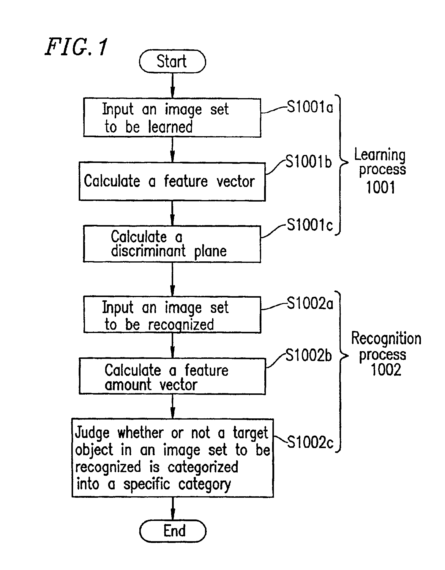
[0064]FIG. 1 is a flowchart showing a procedure of an object recognition method according to the present invention. The object recognition method of the present invention comprises a learning process 1001 (steps S1001a to S1001c) and a recognition process 1002 (steps S1002a to S1002c). Hereinafter, the object recognition method of the present invention is applied to recognition of a human, for example. The procedure of the object recognition method of the present invention will be described. The object recognition method shown in FIG. 1 is executed by an object recognition apparatus 1 which is described later with reference to FIG. 6.

[0065]In step S1001a, sets of images to be learned are input to the object recognition apparatus 1. Unless...


PUM


Abstract

An object recognition apparatus includes an input section for inputting a first image set including a predetermined number of images including a first image representing a first target object using a first attribute and a second image representing the first target object using a second attribute different from the first attribute, a feature vector calculation section for calculating a first feature vector in a feature space having at least one filter output value as a vector component, the at least one filter output value being obtained by applying at least one predetermined image filter to at least one predetermined position in the predetermined number of images in the first image set, and a judgment section for judging whether or not the first target object is categorized into a specific category based on a relationship between the first feature vector and predetermined discriminant parameters.

Description

BACKGROUND OF THE INVENTION[0001]1. Field of the Invention[0002]The present invention relates to an apparatus and method for recognizing an object belonging to a specific category. More particularly, the present invention relates to an apparatus and method for recognizing an object using a plurality of images representing the object in terms of different attributes.[0003]2. Description of the Related Art[0004]Japanese Laid-Open Publication No. 8-287216, entitled “Internal facial feature recognition method”, discloses a technique for recognizing a target object in a plurality of images representing the target object in terms of different attributes. In this conventional technique, internal facial features (e.g., the mouth) are recognized from a far-infrared light (light having a wavelength of 8 to 10 μm) image and a visible light image (from a plurality of images representing a target object in terms of different attributes). A far-infrared light image represents the intensity of far...

Claims


Application Information

Patent Timeline
Patent Type & Authority Patents(United States)
IPC IPC(8): G06K9/00G06K9/62G06V10/143G06V10/36
CPCG06K9/00228G06K9/00362G06K9/2018G06K9/4609G06K9/56G06V40/161G06V40/10G06V10/143G06V10/443G06V10/36
Inventor IMAGAWA, TAROMEKATA, TSUYOSHI
Owner PANASONIC CORP
Learn More