
Symbol synchronizer for impulse noise channels

a synchronizer and impulse noise technology, applied in the field of data communication, can solve the problems of poor performance, incomplete failure, and inability to detect symbols,

Inactive Publication Date: 2005-11-01
ALCATEL-LUCENT USA INC +1
View PDF6 Cites 5 Cited by
  • Summary
  • Abstract
  • Description
  • Claims
  • Application Information

AI Technical Summary

Benefits of technology

[0005]The above problem is addressed by having a symbol synchronizer producing a timing signal based on a control signal which is derived from received samples by using a distance metric function.
[0006]An embodiment is a symbol synchronizer that comprises a distance metric computation module for computing a metric from received samples using a distance metric function within a symbol sampling peri...

Problems solved by technology

When a receiver is not synchronized with the transmitter, the detected symbols are likely to be incorrect.
An important factor that affects the performance of a symbol synchronizer is the type of noise present in the communication channel connecting a transmitter and a receiver.
However, most of the known symbol synchronization techniques assume that the noise is Gaussian and, as such, may perform poorly or fail completely in the presence of non-Gaussian noise.
Unfortunately, the matched filter is generally an optimal detector for Gaussian noise communication channels, but in the presence of non-Gaussian noise, its output may not exhibit a symmetrical shape, which may cause the early-late gate symbol synchronizer to break down, i.e., produce a timing signal which is substantially out of synchronization with the transmitter.

Method used


Image

  • Symbol synchronizer for impulse noise channels
  • Symbol synchronizer for impulse noise channels
  • Symbol synchronizer for impulse noise channels

Examples


Embodiment Construction

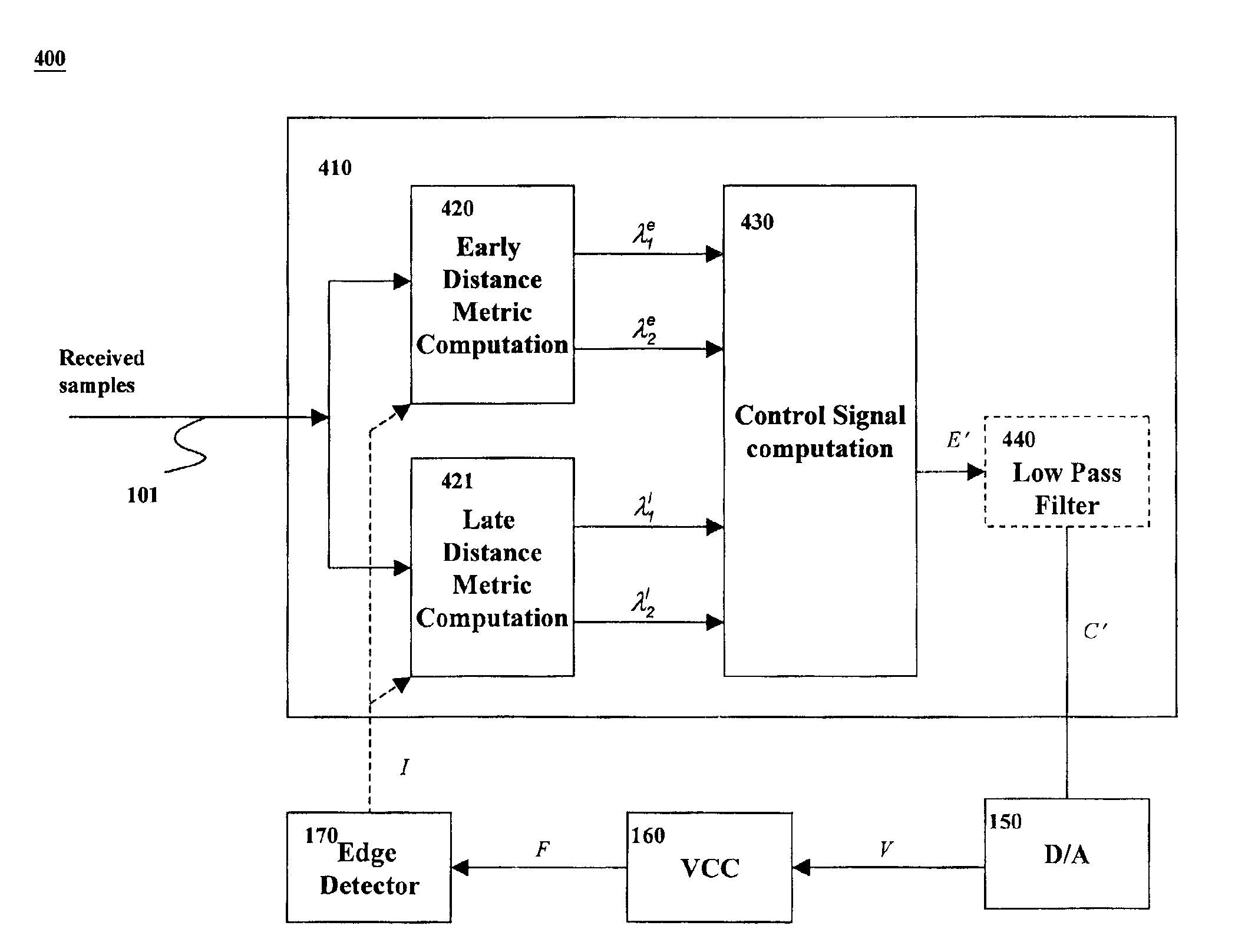
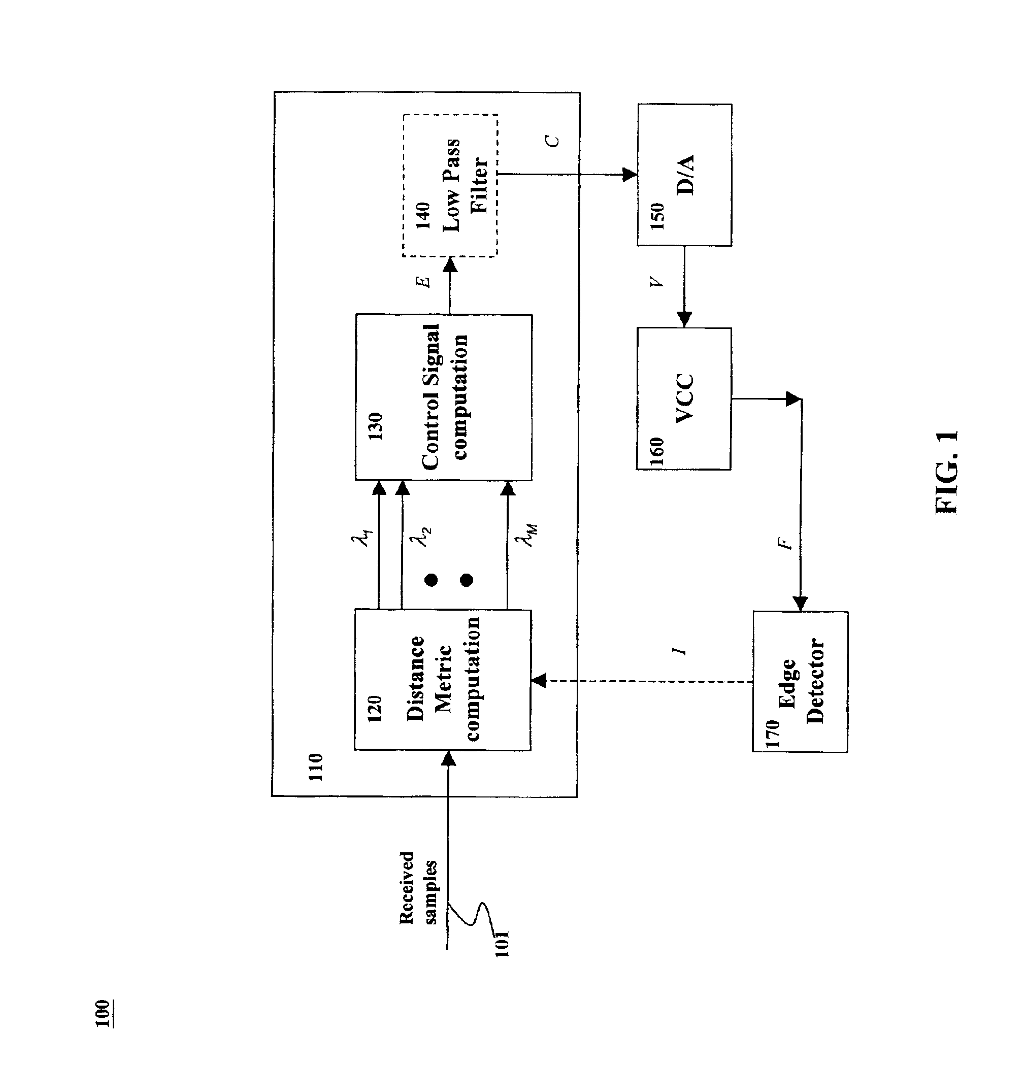
[0014]FIG. 1 shows an illustrative symbol synchronizer 100 in accordance with the principles of the invention. For illustration purposes, an M-point quadrature amplitude modulation (QAM) is used at the transmitter (not shown), i.e., there are M symbols in the constellation and, thus, there are M possible symbols to be detected by symbol synchronizer 100. Symbol synchronizer 100 comprises control signal generator 110, digital-to-analog (D / A) converter 150, voltage-control clock (VCC) 160, and edge detector 170.

[0015]Control signal generator 110 comprises distance metric computation module 120, control signal computation module 130, and optional low pass filter 140. The modules in control signal generator 110 are illustratively implemented as software in an Agere™ DSP16210 digital signal processor. Those modules can also be implemented in one or more digital signal processors (DSPs) or microprocessors, or in one or more application specific integrated circuits (ASICs). Distance metric...


PUM


Abstract

A symbol synchronizer comprises a distance metric computation module for computing a metric from received samples using a distance metric function within a symbol sampling period and based on a timing signal for each of the possible symbols in a constellation, a control signal computation module for selecting a smallest and a second smallest metrics, producing a difference by subtracting the smallest metric from the second smallest metric, and deriving a control signal from the difference, and a voltage-control clock for producing the timing signal based on the control signal.

Description

FIELD OF THE INVENTION[0001]The present invention relates to data communication and, more particularly to synchronization.BACKGROUND OF THE INVENTION[0002]Symbol synchronization is one of the most critical receiver functions. When a receiver is not synchronized with the transmitter, the detected symbols are likely to be incorrect.[0003]An important factor that affects the performance of a symbol synchronizer is the type of noise present in the communication channel connecting a transmitter and a receiver. In many applications such as wireless communications and underwater acoustic channels, the noise is known to be non-Gaussian. However, most of the known symbol synchronization techniques assume that the noise is Gaussian and, as such, may perform poorly or fail completely in the presence of non-Gaussian noise.[0004]For example, one of the most common symbol synchronizers is the early-late gate symbol synchronizer. The underlying idea of an early-late gate symbol synchronizer is to ...

Claims


Application Information

Patent Timeline
IPC IPC(8): H04L7/02
CPCH04L7/0062
Inventor AHMED, WALIDGONZALEZ, JUAN G.MANJI, SALIMPAREDES, JOSE LUIS
Owner ALCATEL-LUCENT USA INC
Learn More