
TCP fast recovery extended method and apparatus

a fast recovery and extended method technology, applied in the field of tcp fast recovery extended method and apparatus, can solve the problems of smooth recovery, most internet loss, and sufficient time available, and achieve the effects of smooth recovery, improved throughput for individual users, and faster recovery

Inactive Publication Date: 2005-10-25
CISCO TECH INC
View PDF5 Cites 59 Cited by
  • Summary
  • Abstract
  • Description
  • Claims
  • Application Information

AI Technical Summary

Benefits of technology

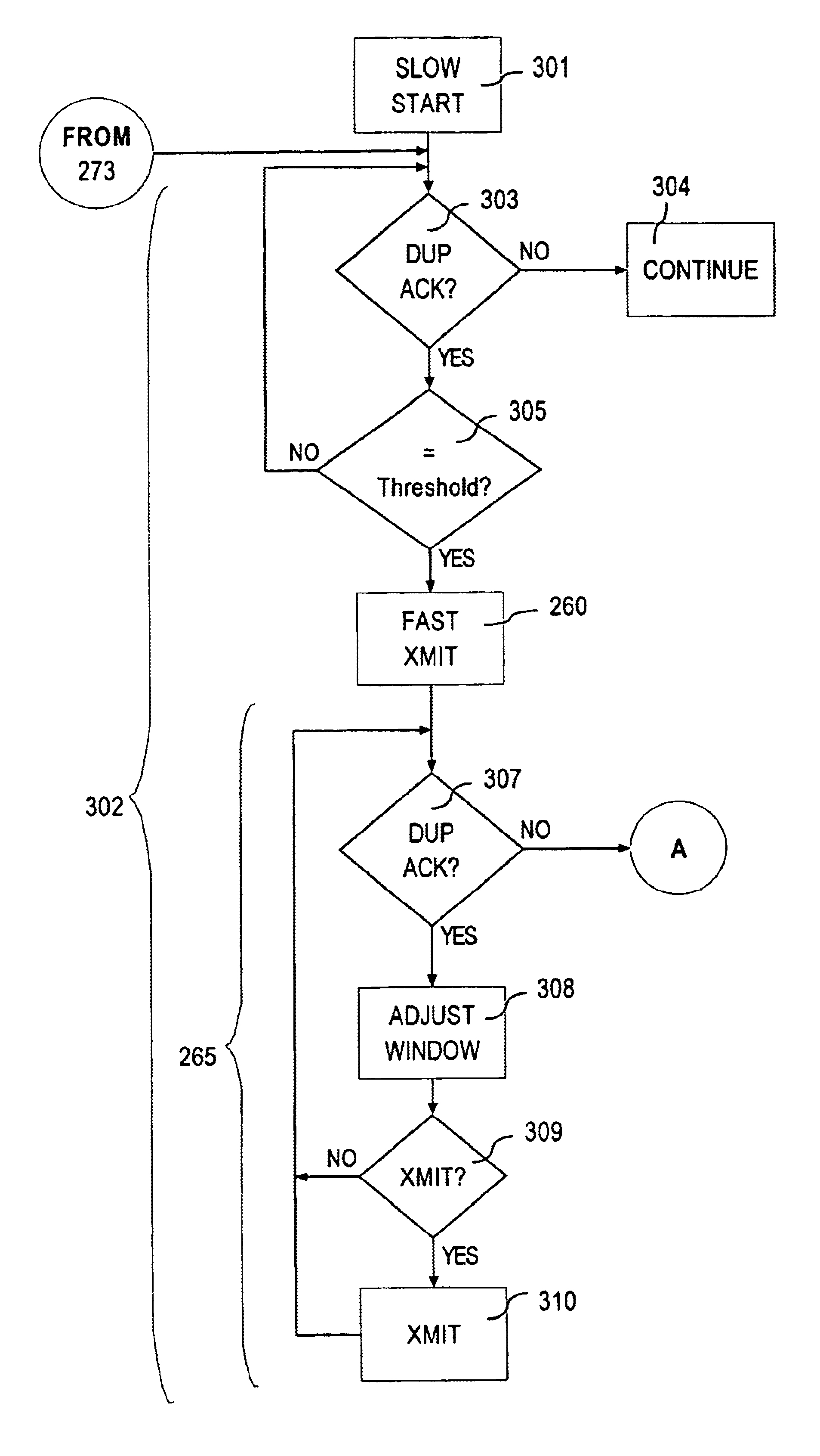
[0021]According to the principles of this invention, a novel fast recovery extended method is used to enhance the performance of TCP fast recovery when multiple segment losses occur within a single round trip time between a TCP sender and a TCP receiver. Unlike the prior art fast recovery technique that worked well in only limited circumstances, the fast recovery extended method enhances recovery for second and subsequent segment losses within a single round trip time.
[0030]Also, only the TCP sender needs to have the fast recovery extended method available. No changes are required of a TCP receiver. The retention and use of the knowledge provided by the number of duplicate acknowledgements results in a smoother and faster recovery from multiple losses in a single round trip time than was previously possible. Consequently, the fast recovery extended method of this invention makes more efficient use of the network, and improves throughput for the individual user.

Problems solved by technology

Most losses on the Internet are caused by congestion as routers run out of buffers and discard incoming traffic.
However, fast recovery does not always result in a smooth recovery when there are multiple lost segments in a single round trip time.
Similarly, if the new drop occurs almost a round trip time after the first drop, there may not be sufficient time available for generation of three duplicate acknowledgements, and again a retransmission timeout occurs.
As network congestion increases, and multiple drops in a single round trip time occur, the performance of network 120 is degraded because fast recovery cannot handle multiple drops in a single round trip time.

Method used


Image

  • TCP fast recovery extended method and apparatus
  • TCP fast recovery extended method and apparatus
  • TCP fast recovery extended method and apparatus

Examples


Embodiment Construction

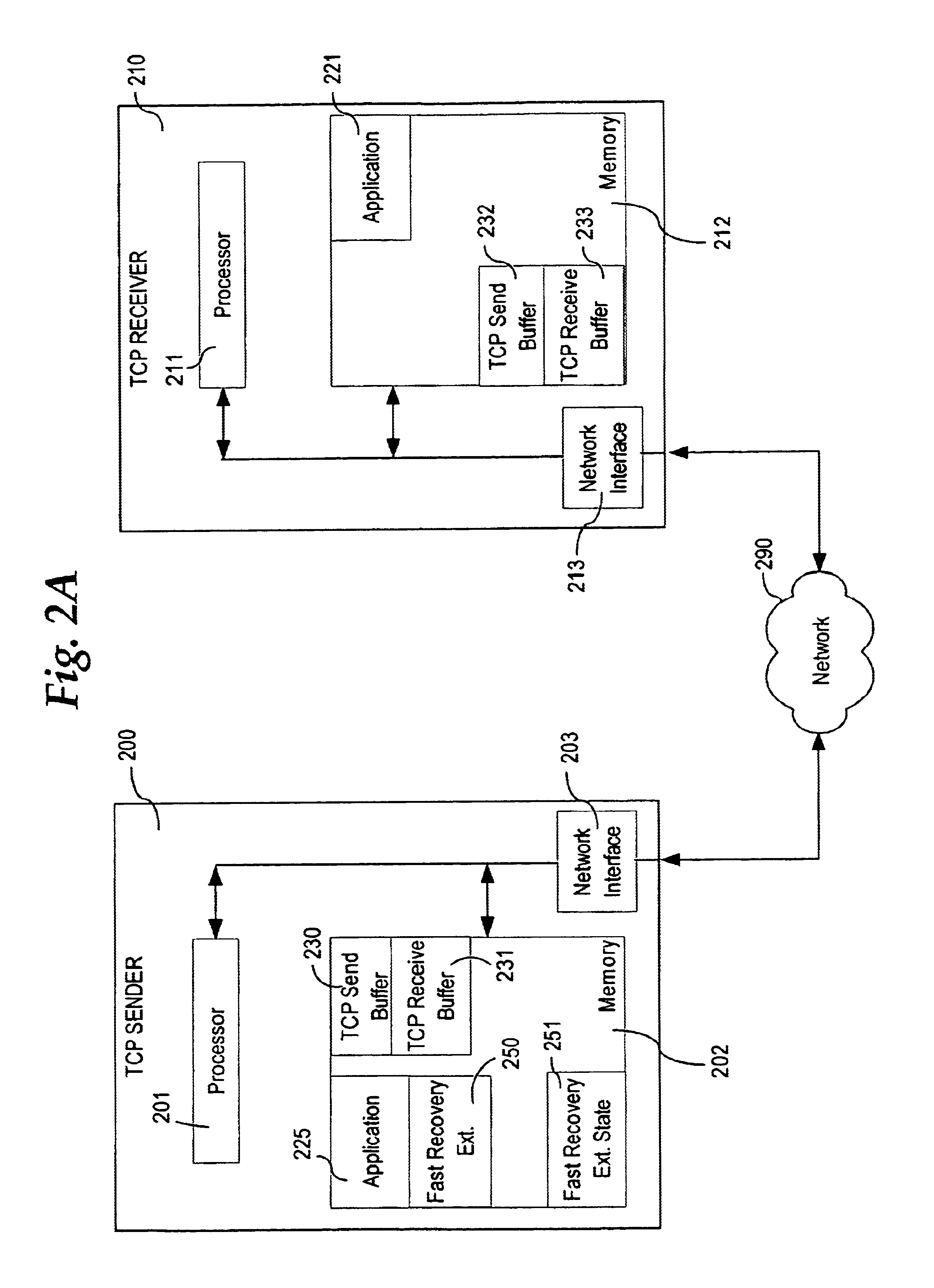
[0050]According to the principles of this invention, a novel fast recovery extended method 250 (FIG. 2A) is used to enhance the performance of TCP fast recovery when multiple segment losses occur within a single round trip time between a TCP sender 200, which is a network device, and a TCP receiver 210. Unlike the prior art fast recovery technique that worked well in only limited circumstances, fast recovery extended method 250 enhances recovery for second and subsequent segment losses within a single round trip time.

[0051]Fast recovery extended method 250 is used by TCP sender 200 upon receipt of an acknowledgement of receipt of new data by TCP receiver 210 that follows receipt of at least a predefined number of duplicate acknowledgement packets from TCP receiver 210. In particular, fast recovery extended method 250 utilizes information in fast recovery extended state data 251 that is stored in a memory 202 to determine the best way to extend fast recovery. Hence, in contrast to th...


PUM


Abstract

A fast recovery extended method is used to enhance the performance of TCP fast recovery when multiple segment losses occur within a single round trip time between a TCP sender and a TCP receiver. A TCP fast recovery process is performed by a TCP sender, and then a TCP fast recovery extended process is performed by the TCP sender upon receiving acknowledgement of receipt of new data from a TCP receiver in the TCP fast recovery process. The fast recovery extended process determines, following receipt of the acknowledgement of receipt of new data, an excess number of duplicate acknowledgements based upon a count of consecutive duplicate acknowledgement packets. The fast recovery extended process takes a network packet transmission recovery action based upon the excess number of duplicate acknowledgements, and then stores the excess number of duplicate acknowledgements as a number of duplicate acknowledgements for further use.

Description

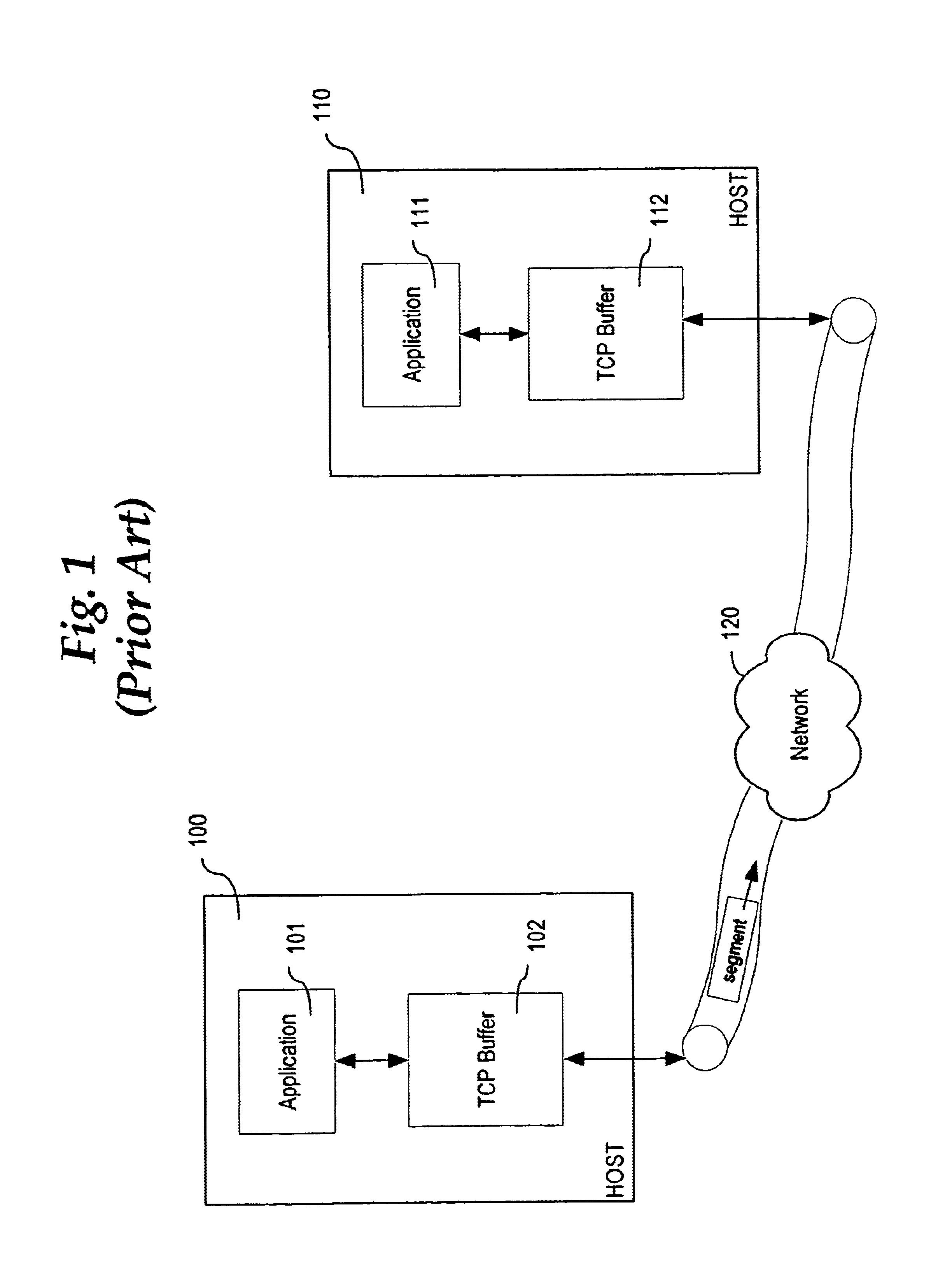
BACKGROUND OF THE INVENTION[0001]1. Field of the Invention[0002]This invention relates generally to methods used in implementation of the network Transmission Control Protocol, and more specifically to congestion control methods used in the Transmission Control Protocol.[0003]2. Description of Related Art[0004]The network Transmission Control Protocol (TCP) is well known. TCP runs only in end systems 100, 110 on a network 120 and not in intermediate network elements such as routers or bridges. The intermediate network elements do not maintain TCP connection state. A TCP connection between end systems 100, 110, sometimes called hosts 100, 110, provides full duplex data transfer between hosts 100, 110. A TCP connection is always point-to-point, i.e., between a single TCP sender and a single TCP receiver.[0005]When a TCP connection is established, two application processes 101, 111 can send data to each other. Data is transmitted in segments. A segment includes header fields and a data...

Claims


Application Information

Patent Timeline
IPC IPC(8): H04L1/16H04L1/18
CPCH04L1/1858H04L1/1874
Inventor BOLTON, DEREK W.
Owner CISCO TECH INC
Learn More