Reciprocating linear actuator
a linear actuator and reciprocating technology, applied in the direction of dynamo-electric machines, electrical devices, metal working devices, etc., can solve the problems of difficult to reduce the size and difficulty in reducing the size of the reciprocating linear actuator, and achieve the effect of less variation, less variation, and less variation
- Summary
- Abstract
- Description
- Claims
- Application Information
AI Technical Summary
Benefits of technology
Problems solved by technology
Method used
Image
Examples
embodiment 1
(Embodiment 1)
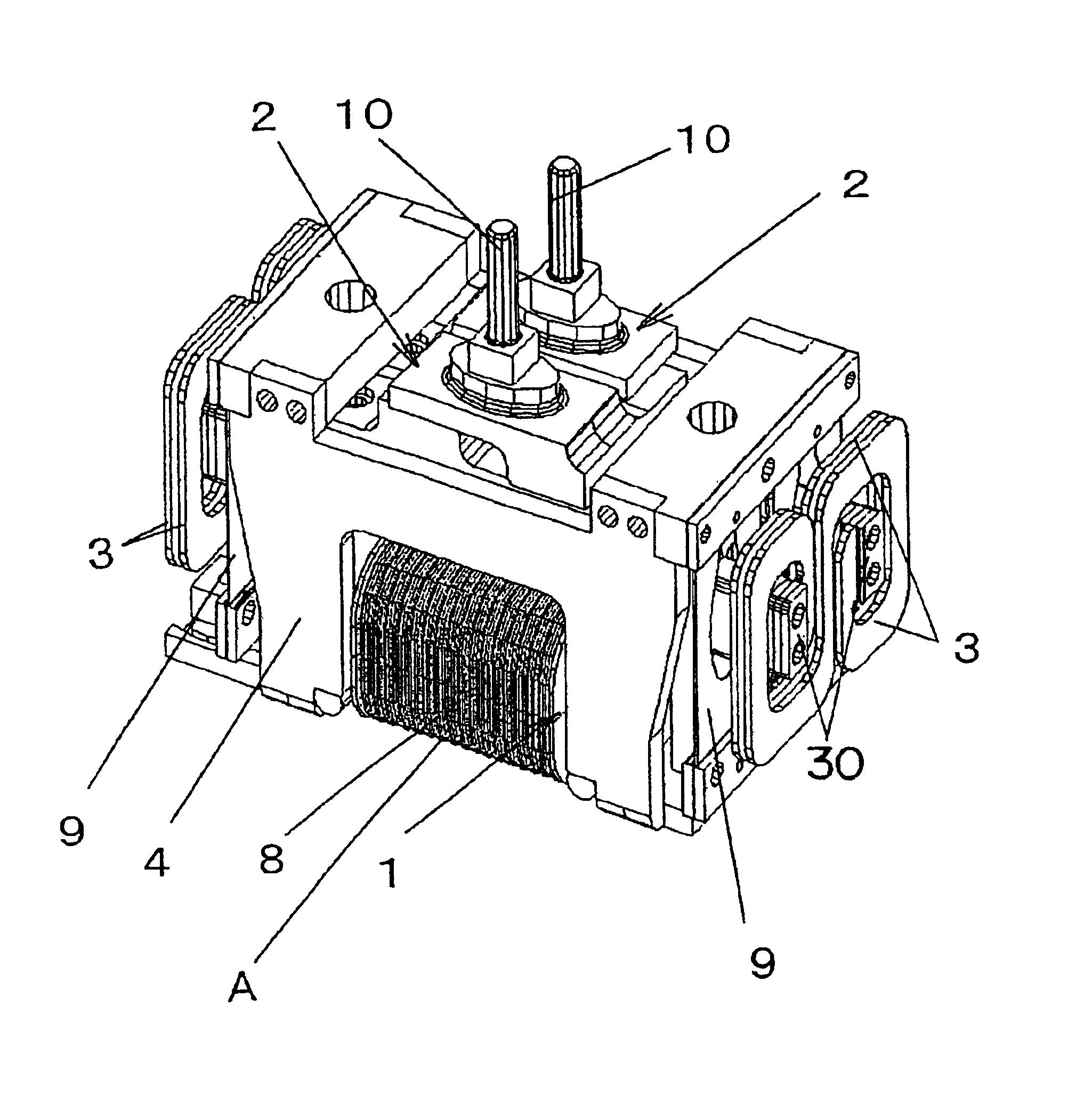
[0038]FIGS. 1 to 4 show a reciprocating linear actuator A, which is used as a drive source for a reciprocatory electric shaver, according to Embodiment 1. This actuator A comprises a stator 1, movable elements 2, a chassis 4, and a connection body 3 connecting the two movable elements 2 and 2.
[0039]The movable element 2 has a permanent magnet 5 and a yoke 6 (back yoke), which are constructed as a unit with a frame member 7. The permanent magnet 5 is bonded to the yoke 6 which is formed from a magnetic material. Further, the movable element 2 has a connection portion 10 to which the movable cutter of an electric shaver is connected.
[0040]The stator 1 is an electromagnet in which a winding 8 is wound around a core, which is a sintered body of magnetic material or a laminated core of iron as magnetic material, and the stator is secured to the chassis 4 with a screw or the like.
[0041]The movable element 2 is suspended from the chassis 4 via a suspension piece 9 made of a f...
embodiment 2
(Embodiment 2)
[0050]FIGS. 5 and 6 show a reciprocating linear actuator according to Embodiment 2. A connection body 3 used in this embodiment is a reverse U-shaped flat spring of which the two ends further extends inward to be connected to the respective movable elements 2 and 2. This connection body 3 also has such a shape that can be drawn with a single stroke on a plane orthogonal to the reciprocating direction of the movable element 2. While the S-shaped connection body in the above embodiment is symmetrical about a point, the connection body 3 in this embodiment is symmetrical about a line, so that it is not directional in shape for facilitating the assembling. The mounting positions 30 of the connection body 3 to the respective movable elements 2 are on the alignment planes of the movable elements 2 at a uniform distance from the centers of gravity G of the respective movable elements 2. Although the mounting position 30 of the connection body 3 is not on the reciprocating dir...
embodiment 3
(Embodiment 3)
[0051]FIGS. 7 and 8 show a reciprocating linear actuator according to Embodiment 3. A connection body 3 used in this embodiment has a S-shaped configuration, in which the two arched ends extend circumferentially to be connected to the respective movable elements 2 and 2. This connection body 3 has such a shape that can be drawn with a single stroke on a plane orthogonal to the reciprocating direction of the movable element 2. The mounting positions 30 of the connection body 3 to the respective movable elements 2 are on the plane (horizontal broken line in FIG. 8) that is orthogonal to the alignment plane of the movable element 2 and parallel to the reciprocating direction as well as including the centers of gravity G of the two movable elements 2. Further, the mounting positions are at a uniform distance from the centers of gravity G of the respective movable elements 2. Although the mounting position 30 of the connection body 3 is not on the reciprocating direction of...
PUM
 Abstract
Description
Claims
Application Information
 - R&D
- Intellectual Property
- Life Sciences
- Materials
- Tech Scout
- Unparalleled Data Quality
- Higher Quality Content
- 60% Fewer Hallucinations
Browse by: Latest US Patents, China's latest patents, Technical Efficacy Thesaurus, Application Domain, Technology Topic, Popular Technical Reports.
© 2025 PatSnap. All rights reserved.Legal|Privacy policy|Modern Slavery Act Transparency Statement|Sitemap|About US| Contact US: help@patsnap.com


