
Wound retraction apparatus and method

a technology for retraction apparatus and wunds, which is applied in the field of wund retraction, can solve the problems of difficult placement, cumbersome use, and difficulty in maintaining the pressure of insufflation gas, and achieve the effects of reducing risk or damage, reducing labor intensity, and facilitating the placement of the wund retraction devi

Inactive Publication Date: 2005-10-25
APPL MEDICAL RESOURCES CORP
View PDF7 Cites 295 Cited by
  • Summary
  • Abstract
  • Description
  • Claims
  • Application Information

AI Technical Summary

Benefits of technology

The present invention provides a surgical wound retractor that allows surgeons to easily locate a retractor and to provide a solid base for an instrument or hand seal during hand-assisted laparoscopic surgery. The retractor removes the tissue pressure from the wrist and protects the tissue at the wound site from abrasion, bacteria or other contaminants. The retractor also opens the wound providing greater access to the operative site for instruments. The invention includes a plurality of retraction elements that exert a radial retraction force on the wound, the force being dependent on the distance separating the first and second rings. The retractor can be easily adjusted to different wound sizes and can provide a stable base for surgical procedures.

Problems solved by technology

Maintaining the pressure of the insufflation gas is difficult when it is also desirable to insert instrumentation through the abdominal wall.
If the surgeon is interested in inserting his or her hand in a hand-assisted laparoscopic procedure, the maintenance of insufflation pressure is even more difficult.
Currently, several devices exist that accomplish this surgical need although they suffer from drawbacks such as difficult placement and cumbersome use.

Method used


Image

  • Wound retraction apparatus and method
  • Wound retraction apparatus and method
  • Wound retraction apparatus and method

Examples


Embodiment Construction

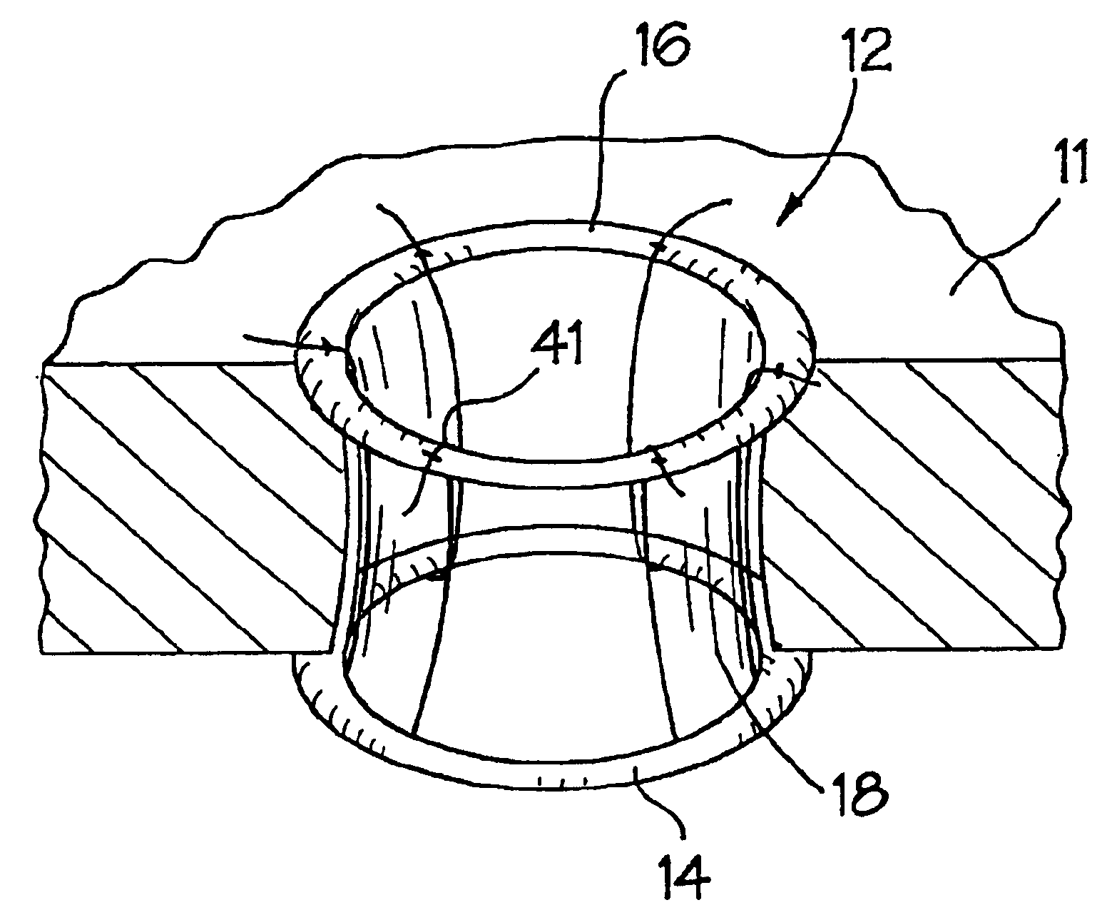
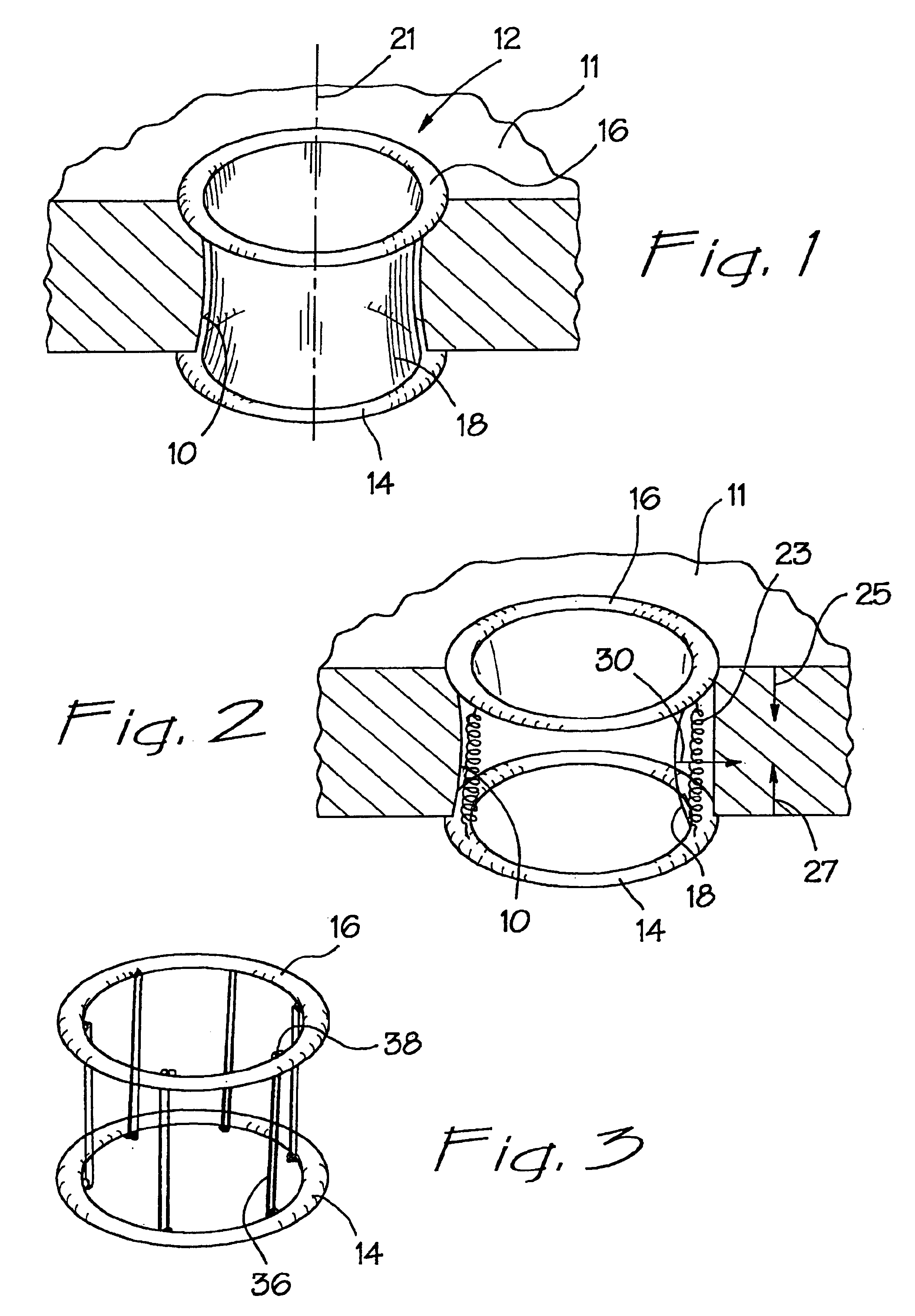
[0048]The basic concept of retracting and protecting a wound site is illustrated in the prospective view of FIG. 1 wherein a wound 10 is formed in an abdominal wall 11. In this embodiment, a retractor 12 uses two rings 14 and 16 which are fixed to an elastic sheath 18. The sheath 18 has a generally cylindrical configuration and is disposed along an axis 21. The rings 14 and 16 are disposed in respective planes which extend radially of the axis 21.

[0049]The sheath 18 has elastomeric properties, but in its natural, unstretched state the two rings 14 and 16 are separate by a natural distance. The lower ring 14 is placed interiorly of the abdominal wall 11 and the upper ring 14 is stretched beyond the natural distance away from the lower ring. Once the elastic sheath 18 has been stretched to a distance greater than the abdominal wall thickness, the upper ring 16 is placed on the surface of the skin.

[0050]Since the diameters of the rings 14, 16 are greater than that desired for the wound...


PUM


Abstract

A surgical wound retractor is adapted to dilate a wound stretchable to a desired diameter, the retractor includes a first ring having a diameter greater than that desired for the wound and being adapted for disposition interiorly of the wound. A second ring has a diameter greater than that desired for the wound and is adapted for disposition exteriorly of the wound. A plurality of retraction elements are disposed in a generally cylindrical relationship to each other, between the first ring and the second ring. These elements extend through the wound to exert a radial retraction force on the wound which is dependent on the distance separating the first ring and the second ring. Retraction elements, both distensible and non-distensible are contemplated with appropriate attachment elements at the rings to provide for variations in the retraction force. With a suitable retraction sleeve, a third ring can be provided to form a circumferential retainer to vary the retraction force. Rings can also be made inflatable or self-expanding to vary the retraction force. An associated method includes the step of rolling the second ring circumferentially of the third ring to form the circumferential retainer.

Description

CROSS REFERENCE TO RELATED APPLICATIONS[0001]This is a non-provisional application claiming the priority of PCT application Ser. No. PCT / US01 / 50742, filed on Oct. 20, 2000, and entitled “Wound Retraction Apparatus and Method,” which is fully incorporated herein by reference.BACKGROUND OF THE INVENTION[0002]1. Field of Invention[0003]This invention-relates generally to wound retraction and more specifically to wound retraction in a laparoscopic surgical procedure.[0004]2. Discussion of the Related Art[0005]During laparoscopic surgery, it is desirable to inflate the abdominal cavity in order to increase the volume of the working space. This is accomplished with an insufflation gas which must be maintained at a pressure sufficient to inflate the abdomen. Maintaining the pressure of the insufflation gas is difficult when it is also desirable to insert instrumentation through the abdominal wall. If the surgeon is interested in inserting his or her hand in a hand-assisted laparoscopic pro...

Claims


Application Information

Patent Timeline
Patent Type & Authority Patents(United States)
IPC IPC(8): A61B17/34A61B17/02
CPCA61B1/32A61B17/0293A61B17/3423A61B17/3431A61B2017/3484
Inventor EWERS, RICHARD C.BRUSTAD, JOHN R.PINGLETON, EDWARD D.HILAL, NABILADLPARVAR, PAYAMTAYLOR, SCOTTDULAK, GARY R.DUNN, MICHAEL J.MORALES, NORMAN L.HART, CHARLES C.BOWES, ROBERT R.
Owner APPL MEDICAL RESOURCES CORP
Learn More