
Projector with spectral filter

a spectral filter and projector technology, applied in the field of projectors with spectral filters, can solve problems such as less than optimal gamu

Inactive Publication Date: 2005-10-18
HEWLETT PACKARD DEV CO LP
View PDF19 Cites 22 Cited by
  • Summary
  • Abstract
  • Description
  • Claims
  • Application Information

AI Technical Summary

Problems solved by technology

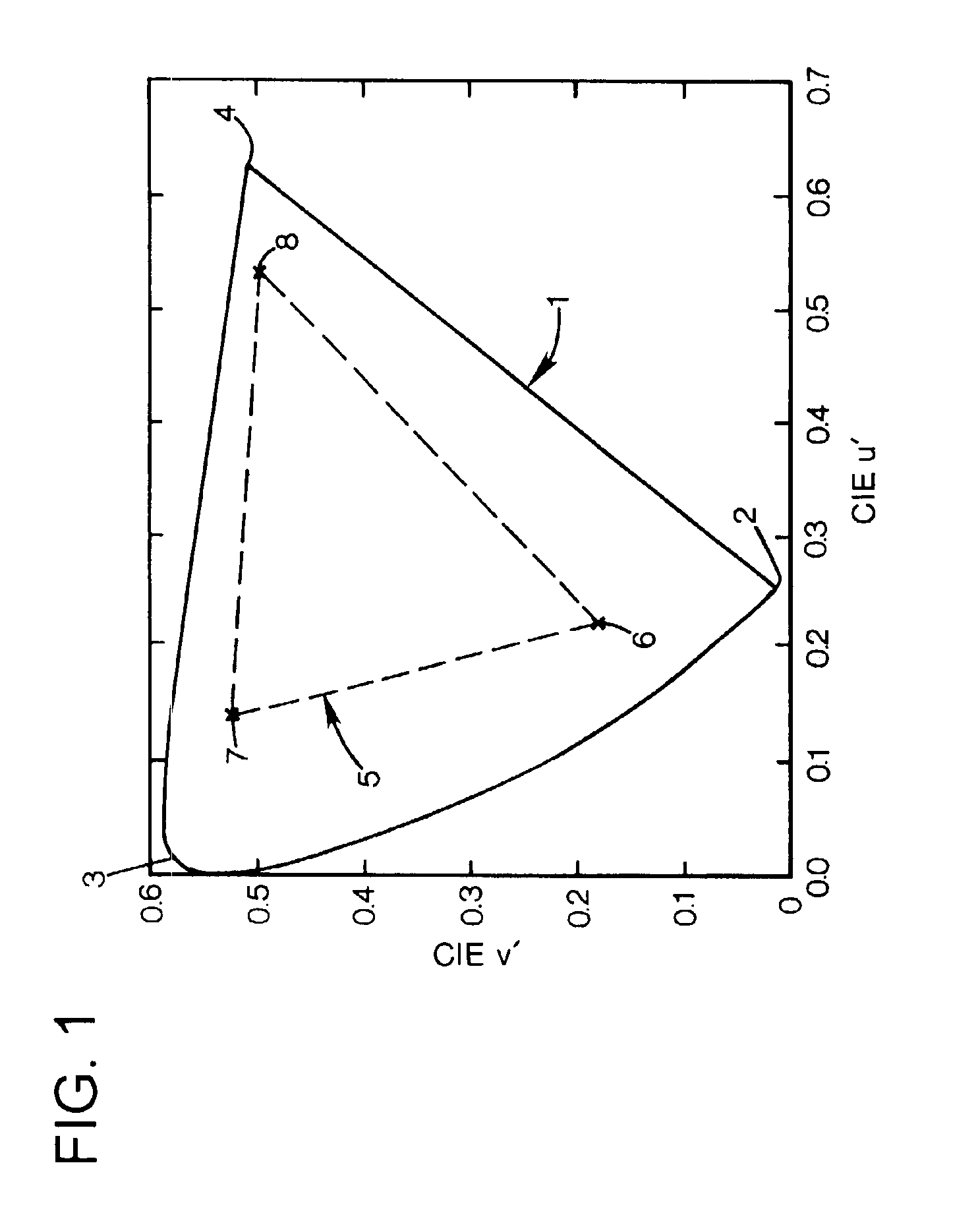
Where color projected pixels are not mono-chromatic, but have spectral power distributions within the color spectral bands, the gamut is less than optimal.

Method used


Image

  • Projector with spectral filter
  • Projector with spectral filter
  • Projector with spectral filter

Examples


Embodiment Construction

[0017]In the following detailed description and in the several figures of the drawing, like elements are identified with like reference numerals.

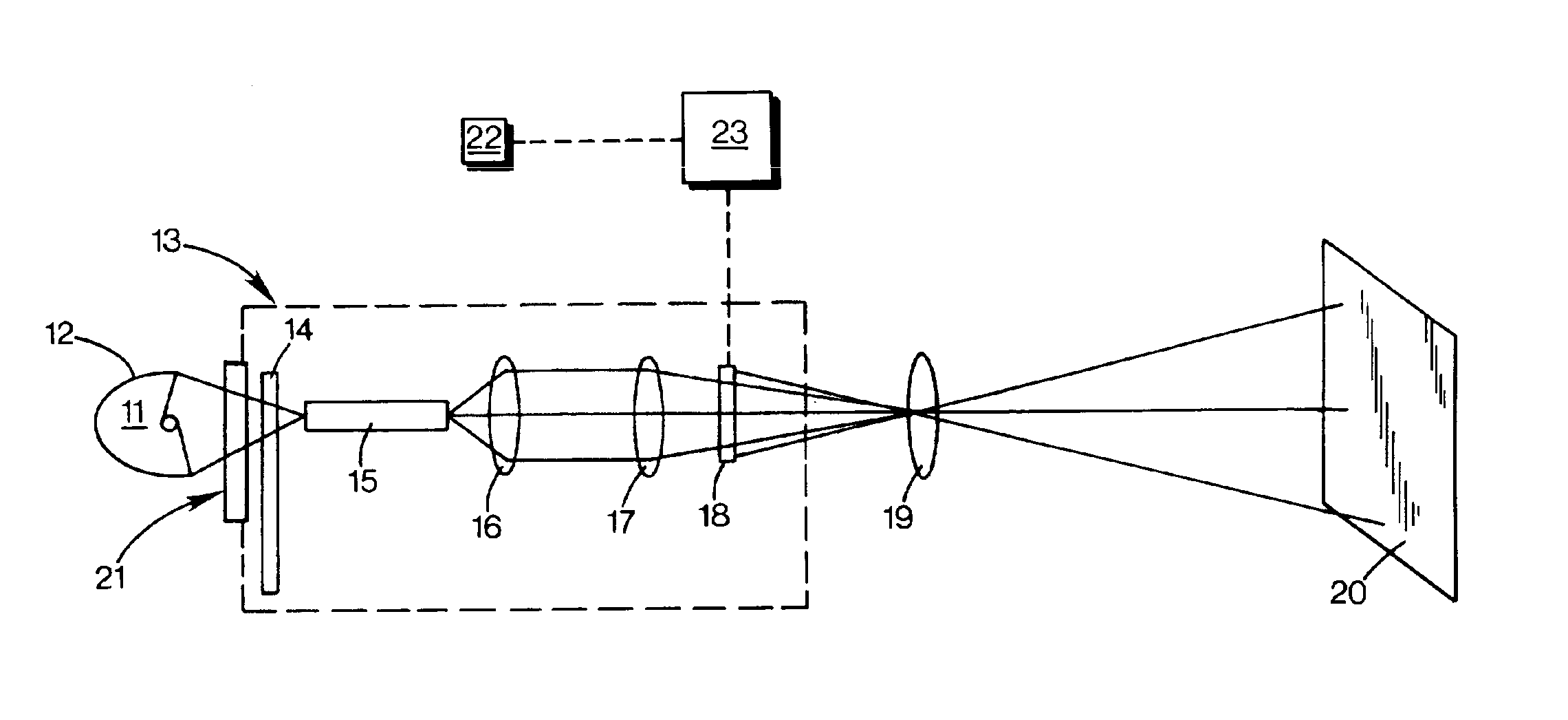
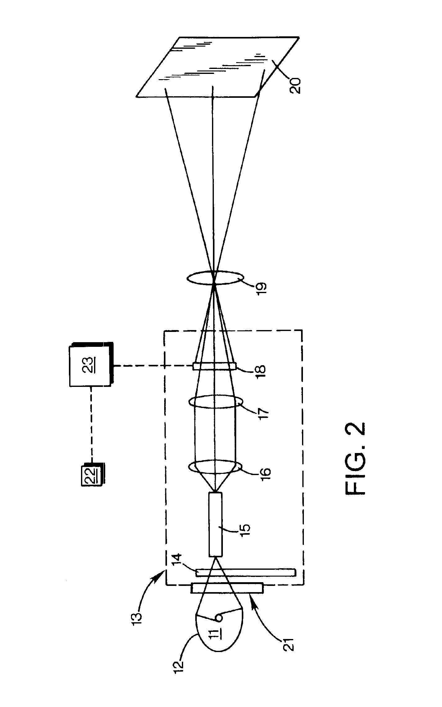
[0018]A light source for a projector has a spectral power distribution. The spectral power distribution has energy distributed throughout the visible spectrum. A modulator modulates light from the light source to output pixels, the pixels comprising projected pixels in a plurality of color spectral color bands, typically blue, green and red and may include a white pixel.

[0019]FIG. 1 is a chromaticity diagram. An idealized projector with mono-chromatic primary color projected pixels would have an idealized gamut 1. The idealized projector would be able to produce all colors within the approximately triangular area with corners at the mono-chromatic blue, green and red primary colors 2-4. The approximate gamut for an exemplary non-uniform light source includes colors within the approximately triangular area 5 with corners at the non-monochrom...


PUM


Abstract

A projector projects pixels to form an image in accordance with image data. The projector includes a modulator which modulates light from a light source and outputs projected pixels in a plurality of color spectral bands. The projector has a light source with a non-uniform spectral power distribution with spectral energy within each of the plurality of color spectral bands. A first notch filter removes spectral energy from a first spectral range within a first color spectral band to improve gamut.

Description

BACKGROUND OF THE DISCLOSURE[0001]A projector projects light from a light source as modulated by a spatial light modulator or object to form an image on a viewing surface. The image is made up of pixels spatially arranged to form an image. Each pixel is created with color characteristics such that an image formed by the properly spatially arranged pixels corresponds to an image represented in image data. The pixels are made up of a plurality of projected pixels that are spatially or temporally combined to give the pixel the desired color characteristics. The projected pixels are created in a plurality of colors, typically blue, green and red or blue, green, red and white.[0002]The range of colors that can be represented by combining projected pixels of given colors is known as the gamut. In an idealized projector, the projected pixels might be mono-chromatic, single-wavelength primary colors, for instance, blue, green and red. These colors would combine to make all of the colors pos...

Claims


Application Information

Patent Timeline
Patent Type & Authority Patents(United States)
IPC IPC(8): G02B27/14G03B21/00G02B5/28G03B21/20H04N9/31
CPCG02B5/289G03B21/20H04N9/3114H04N9/315H04N9/3197
Inventor PATE, MICHAEL A
Owner HEWLETT PACKARD DEV CO LP
Learn More