
Quality monitoring system for building structure, quality monitoring method for building structure and semiconductor integrated circuit device

a technology of quality monitoring system and building structure, applied in the direction of liquid/fluent solid measurement, mechanical actuation of burglar alarm, instruments, etc., can solve the problems of inability to effectively solve problems, inability to detect whether inadequate concrete is cast or not, and the concrete becomes very fragile and starts to flake in time much shorter than the design life. , to achieve the effect of low pri

Inactive Publication Date: 2005-09-27
HITACHI LTD
View PDF12 Cites 73 Cited by
  • Summary
  • Abstract
  • Description
  • Claims
  • Application Information

AI Technical Summary

Benefits of technology

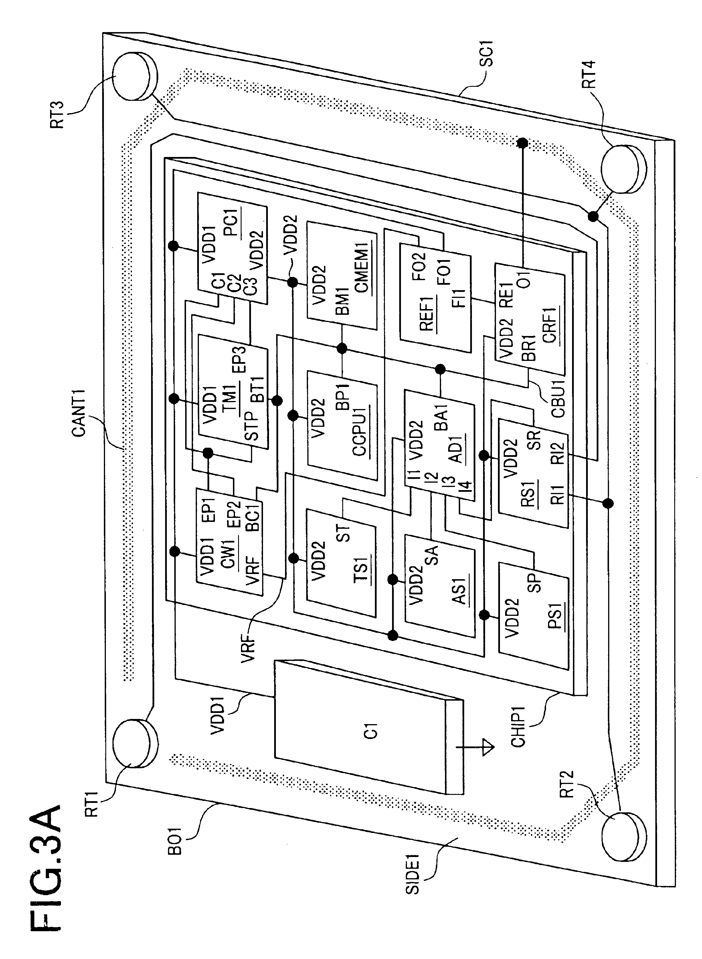
[0032]Further, another object of the invention is to provide a semiconductor integrated circuit device in which an electric power generator, a sensor, CPU, a memory and a radio interface are built to realize the above-mentioned monitoring system and which can permanently monitor the quality of concrete since concrete paste is prepared.
[0033]Further, another object of the invention is to provide a quality monitoring system for building structure and a quality monitoring method for building structure which enable quality control and quality checking in concrete paste preparation, concrete casting and curing and a semiconductor integrated circuit device used for them.
[0034]Further, another object of the invention is to provide a quality monitoring system for building structure and a quality monitoring method for building structure which can realize quality control and quality checking in concrete paste preparation, concrete casting and curing at a low price without using a high-priced sensor such as an optical fiber sensor and a semiconductor integrated circuit device used for them.
[0035]Further, another object of the invention is to provide a quality monitoring system for building structure and a quality monitoring method for building structure in which a sensor is built in the building structure and is not required to be connected to a cable such as an optical fiber cable and a metal cable and which is free from insufficiency by the disconnection of a cable and a semiconductor integrated circuit device used for them.

Problems solved by technology

That is, it is considered that as inadequate concrete paste is used, a chloride ion included in sea sand corrodes the steel structure of foundation, further, a part from which moisture in the concrete paste is evaporated becomes void, as a result, the concrete becomes very fragile and starts to flake in time greatly shorter than a designed life.
In the meantime, the quality monitoring system for building structure and the monitoring method disclosed in the patent document 1 and the nonpatent documents 1 and 2 are basically the monitoring system for building structure already constructed or the monitoring method and they cannot be effective means to solve the problems.
Particularly, it is impossible to detect whether inadequate concrete is cast or not immediately on the spot.
Therefore, there is a problem that even if inadequate concrete is used in construction, inside steel structure and others are extremely deteriorated after ten years or more elapse since the construction and after flaking and collapse start or immediately before they start, it is known that inadequate concrete material is used.
However, in the case of the monitoring system in this document, it cannot be measured until building structure is completed and sensors built in the building structure are connected to measurement equipment.
That is, there is a problem that the monitoring system and the monitoring method disclosed in this document cannot be used for quality control and quality checking in concrete paste preparation, concrete casting and curing.

Method used


Image

  • Quality monitoring system for building structure, quality monitoring method for building structure and semiconductor integrated circuit device
  • Quality monitoring system for building structure, quality monitoring method for building structure and semiconductor integrated circuit device
  • Quality monitoring system for building structure, quality monitoring method for building structure and semiconductor integrated circuit device

Examples


first embodiment

[0060]FIG. 1 shows one embodiment of a quality monitoring system for building structure according to the invention. As shown in FIG. 1, the quality monitoring system for building structure according to the invention is composed of an inspection device (RC1) specific to the invention and semiconductor integrated circuit devices specific to the invention, that is, monitoring chips (SC1 to SC10) buried in concrete (CON1) forming a wall and a floor of building structure (BUL1) when concrete paste is prepared as described later. If necessary, a management server (SV10) installed inside the building structure BUL1 or outside BUL1 may be also used. In FIG. 1, an example that ten monitoring chips are used is shown, however, it is an example for explanation and actual use is not limited to the example.

[0061]The inspection device (RC1) specific to the invention is composed of an antenna (ANT1), a radiocommunication interface (RF1), a processor (CPU1), a memory (MEM1), a secondary storage (HDD...

second embodiment

[0137]In the first embodiment, the method of configuring the monitoring system according to the method of mixing the monitoring chip according to the invention when concrete paste is prepared according to the procedure shown in FIG. 4 is described. In the meantime, in this embodiment, an example in which the quality monitoring system for building structure, the quality monitoring method for building structure and the monitoring chip according to the invention are applied to the existing building structure will be described (FIG. 17). In such a case, first, in a monitoring chip installation routine P135, this monitoring chip is installed in building structure. Various installation methods are conceivable, however, typically, as shown in FIG. 18, installing holes (HL1 to HL7) are made in a wall or a floor of concrete CON1 and monitoring chips (SC1 to SC7) are installed. Further, the installing holes HL1 to HL7 are sealed with resin (RES1 to RES7) such as epoxy resin. To prevent this m...

third embodiment

[0139]In the first embodiment, the example in which the monitoring system is configured by the monitoring chip which can be eternally operated by the built-in electric power generator as shown in FIG. 3 is described. In the meantime, as already described many times, it is the quality of concrete when concrete paste is prepared that has the greatest effect upon the quality of concrete. That is, depending upon an object, a case that only P100 to P120 and P210 to P220 shown in FIG. 4 have only to be monitored also exists.

[0140]FIGS. 19A to 19C show an example of the configuration of a second monitoring chip according to the invention suitable for the object. As shown in FIG. 19, in this monitoring chip, differently from the example shown in FIG. 3, a button battery BA1 is mounted in place of the semiconductor integrated circuit for generating electric power. More detailedly, a first semiconductor integrated circuit CHIP1 is mounted on the upper surface (SIDE1) of a substrate BO1, the b...


PUM


Abstract

A low cost system and method are provided for long-term monitoring of the quality of a building structure utilizing a semiconductor integrated circuit device buried in the structure. A monitoring chip includes a sensor, a microprocessor, a memory, a radio interface, an electric power controller and an electric power generator. The monitoring chip intermittently receives power to intermittently monitor information such as whether concrete is adequately cured, whether the quantity of moisture and chloride ions in concrete paste is adequate, or whether a state of stress inside concrete is in question. Temperature sensors, electric resistance sensors and pressure sensors respectively built in the monitoring chip use the built-in electric power generator as a power source, and the system store any abnormal measured values in a built-in memory. Collected quality data is transmitted according to an external request to indicate building structure quality.

Description

FIELD OF THE INVENTION[0001]The present invention relates to a quality monitoring method for building structure constructible at a low cost, a monitoring system and a semiconductor integrated circuit device for the monitoring system required for realizing them.BACKGROUND OF THE INVENTION[0002]Recently, in building structure formed by concrete such as a tunnel, an accident in which concrete flakes comes into question and the enhancement of the quality of concrete building structure is severely demanded. To realize it, technique for promptly realizing the quality checking of building structure at a low cost is essential. Therefore, many methods of semiautomatically inspecting the quality of building structure nondestructively by an external inspection device are proposed.[0003]In the meantime, a method of building various sensors in building structure beforehand when the building structure is constructed, constantly measuring / monitoring physical quantity such as stress by the sensors ...

Claims


Application Information

Patent Timeline
IPC IPC(8): G01N33/38
CPCG01N33/383
Inventor YAMASHITA, SHUNZOSUZUKI, KEIARITSUKA, TOSHIYUKINAKANO, SADAKI
Owner HITACHI LTD
Learn More