Eureka AIR delivers breakthrough ideas for toughest innovation challenges, trusted by R&D personnel around the world.

Light module for air treatment units

a technology of air treatment unit and light module, which is applied in the direction of material analysis using wave/particle radiation, light support device, disinfection, etc., can solve the problems of difficult safe operation and maintenance of the system employing the technology, pain in the eye, and mild to severe redness of the skin, so as to prevent exposure to uv light, block much of uv-c energy, and maintain the correct airflow rate

Inactive Publication Date: 2005-09-27
STERI LUS
View PDF4 Cites 9 Cited by
  • Summary
  • Abstract
  • Description
  • Claims
  • Application Information

AI Technical Summary

Benefits of technology

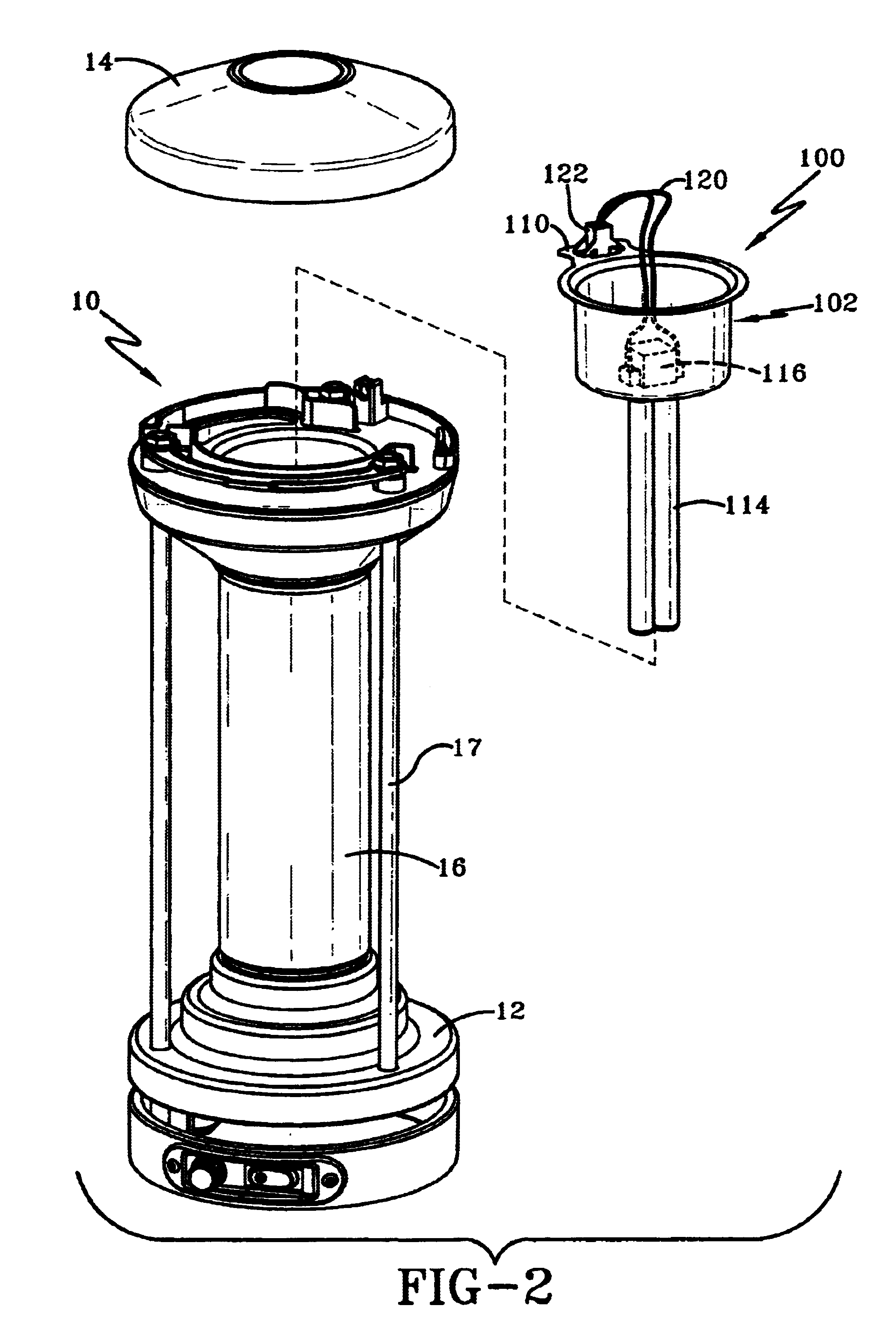
[0006]In a preferred embodiment, the ultraviolet light module is intended to be a replaceable unit in an air treatment device that employs ultraviolet light. Because exposure to UV light should be avoided, the ultraviolet light module allows for safe replacement of spent ultraviolet light sources (e.g., UV light bulbs). Rather than having to access and manipulate the light source directly to replace it when it is spent or otherwise faulty, the entire module can be removed. Due to its design, when removing a module for any reason, the power to the UV light source is disconnected before the module is removed, such that the person servicing the air treatment device is not likely to directly expose himself to a powered UV light source. Similarly, when replacing one module with another, the module is fitted to the air treatment duct before the power to the UV light source is engaged (at the connector and module power socket), and the person replacing the module is not likely to directly expose himself to a powered UV light source. In one embodiment, a power switch is located in the top cap of the air treatment device and when the power switch is adjusted to an “off” position, no power flows to the UV light source. This provides an additional safeguard to ensure that the person servicing the air treatment device is not likely to directly expose himself to a powered UV light source.

Problems solved by technology

A primary limitation on the use of UV-C energy sources for ultra violet germicidal irradiation (UVGI) is the difficulty in safely operating and maintaining systems employing the technology.
Short-wave, high-energy UV-C radiation, which has a wavelength from about 100 to 280 nanometers, can cause mild to severe reddening of the skin and painful injury to the eye.
However, because exposure to UV light is harmful, especially direct exposure to the eyes, there is a need to design replacement UV light sources with safety features that prevent such direct exposure to UV light.

Method used


Image

  • Light module for air treatment units
  • Light module for air treatment units
  • Light module for air treatment units

Examples


Embodiment Construction

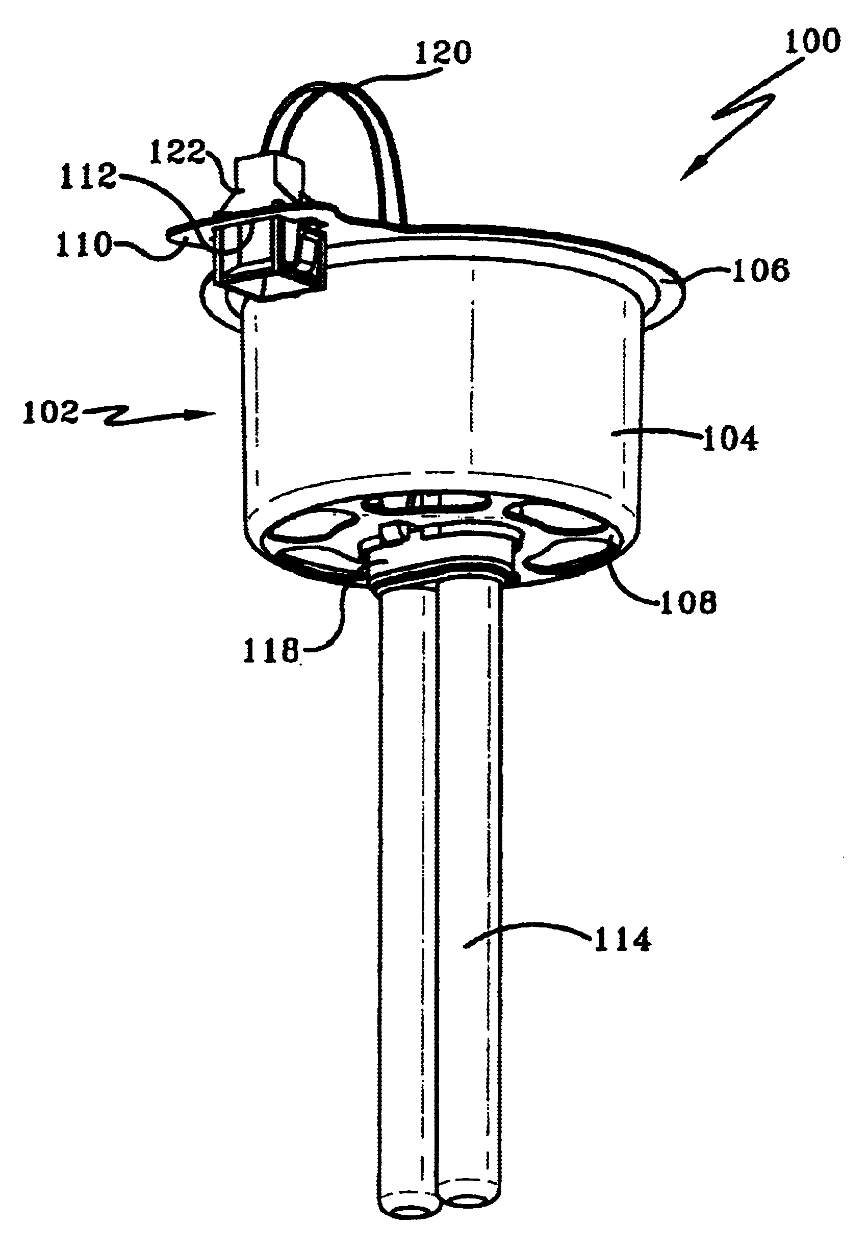
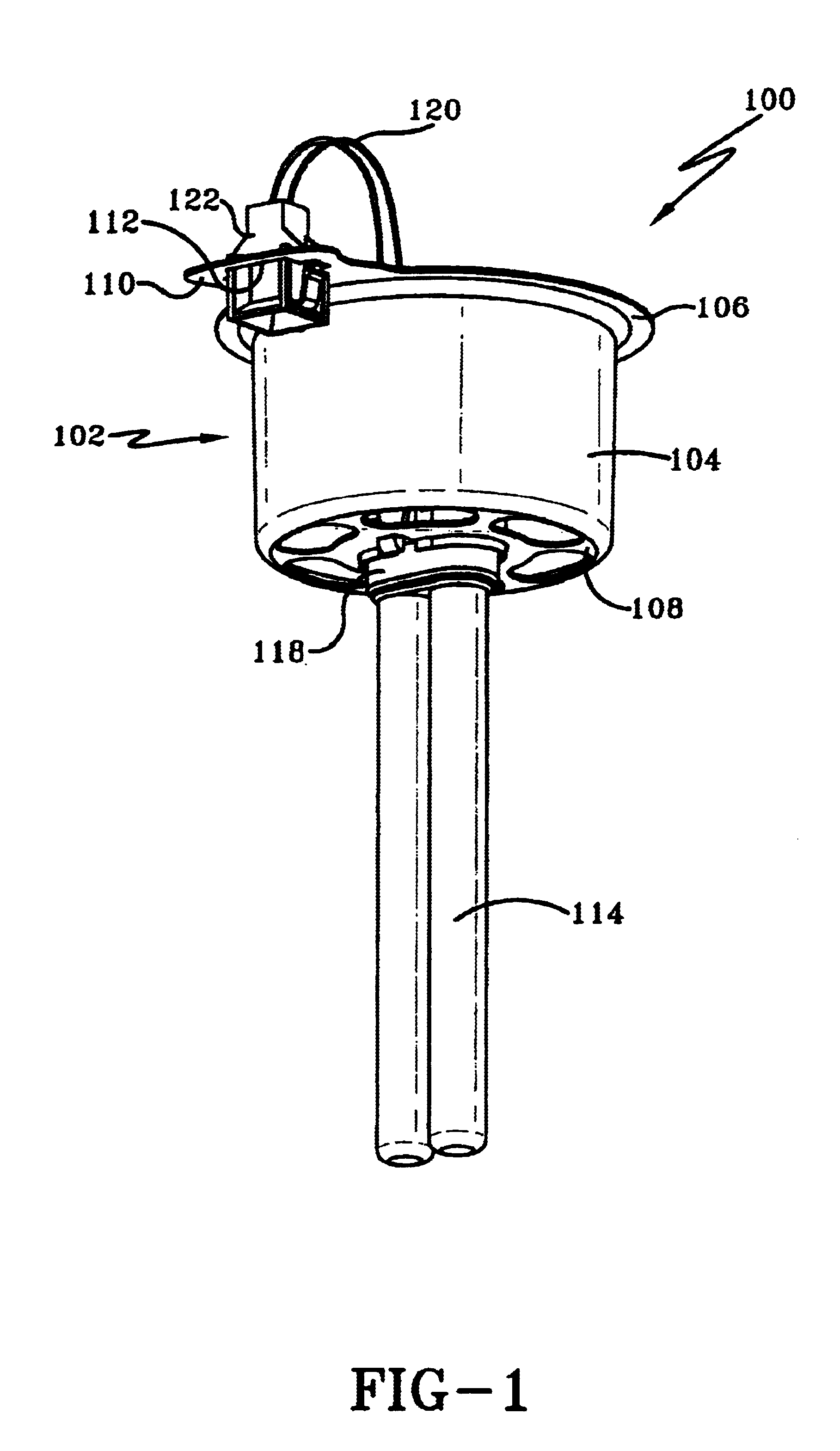
[0015]Referring now to FIG. 1, a light module according to this invention is shown and designated generally by the numeral 100. Light module 100 includes a housing 102 defined by a sidewall 104 extending between a lip 106 and baffle 108. A connector flange 110 with an aperture 112 is formed as part of housing 102, and preferably is formed in lip 106, as shown.

[0016]A UV light source 114 is fixed to baffle 108. As used herein, “fixed” is not necessarily to be understood as defining that UV light source 114 is directly fixed to baffle 108. Rather, in preferred embodiments, such as that shown, UV light source 114 is bonded to light source socket 116 (shown in FIG. 3) to be integral therewith, light source socket 116 is bonded to one side of baffle 108, and UV light source 114 extends through an aperture 118 in baffle 108 to extend on the other side thereof. Although not directly fixed to baffle 108, UV light source is considered “fixed” thereto inasmuch as its position is substantially...


PUM

PropertyMeasurementUnit
wavelengthaaaaaaaaaa
wave lengthaaaaaaaaaa

Abstract

The present invention provides an air treatment unit including a module power socket; an air treatment duct having an interior defining an air path; and an ultraviolet light module that selectively engages the air treatment duct, the ultraviolet light module including a housing having a baffle; an integral ultraviolet light source and light source socket, the ultraviolet light source being fixed to and extending through the baffle; and a connector that selectively mates with the module power socket, the connector being in power transmissive communication with the light source socket, wherein, when the ultraviolet light module selectively engages the air treatment duct and the connector selectively mates with the module power socket, the ultraviolet light module cannot be fully removed from its engagement with the air treatment duct without disconnecting the power.

Description

TECHNICAL FIELD[0001]The present invention generally relates to air treatment systems employing ultraviolet (UV) energy, particularly UV-C energy in the range of about 100 to about 280 nanometers, to disable various airborne microorganisms, including bacteria cells, virus cells, and mold spores. More particularly, this invention relates to an ultraviolet light module for use in air treatment systems, wherein the module provides safety features for preventing harmful exposure to UV energy.BACKGROUND OF THE INVENTION[0002]UV-C energy sources have been used by hospitals, microbiology labs, and food and water and other industries to disable microorganisms that are airborne and / or on work surfaces and equipment and the like. Generally, UV energy sources have been incorporated into irradiation systems and air circulation and ventilation systems to expose harmful microorganisms to UV-C energy in order to reduce the potential for exposure to such microorganisms.[0003]A primary limitation on...

Claims


Application Information

Patent Timeline
Patent Type & Authority Patents(United States)
IPC IPC(8): A61L9/18A61L9/20A62B11/00A61L9/015
CPCA61L9/015A61L9/20F24F2003/1667F24F8/22
Inventor MCELLEN, JOHN J.
Owner STERI LUS
Why Eureka
Eureka Blog
Learn More