
Optical add/drop arrangement for ring networks employing wavelength division multiplexing

a wavelength division multiplexing and add/drop technology, applied in multiplex communication, fault recovery arrangements, electromagnetical repeaters, etc., can solve the problems of complex traffic management in the metropolitan area network, outgrown the capabilities and capacity of sonet rings, and implemented wdm or dwdm in metropolitan area networks, etc., to reduce interference between optical channels, low optical losses, cost and optical losses

Inactive Publication Date: 2005-09-20
LUCENT TECH INC
View PDF22 Cites 32 Cited by
  • Summary
  • Abstract
  • Description
  • Claims
  • Application Information

AI Technical Summary

Benefits of technology

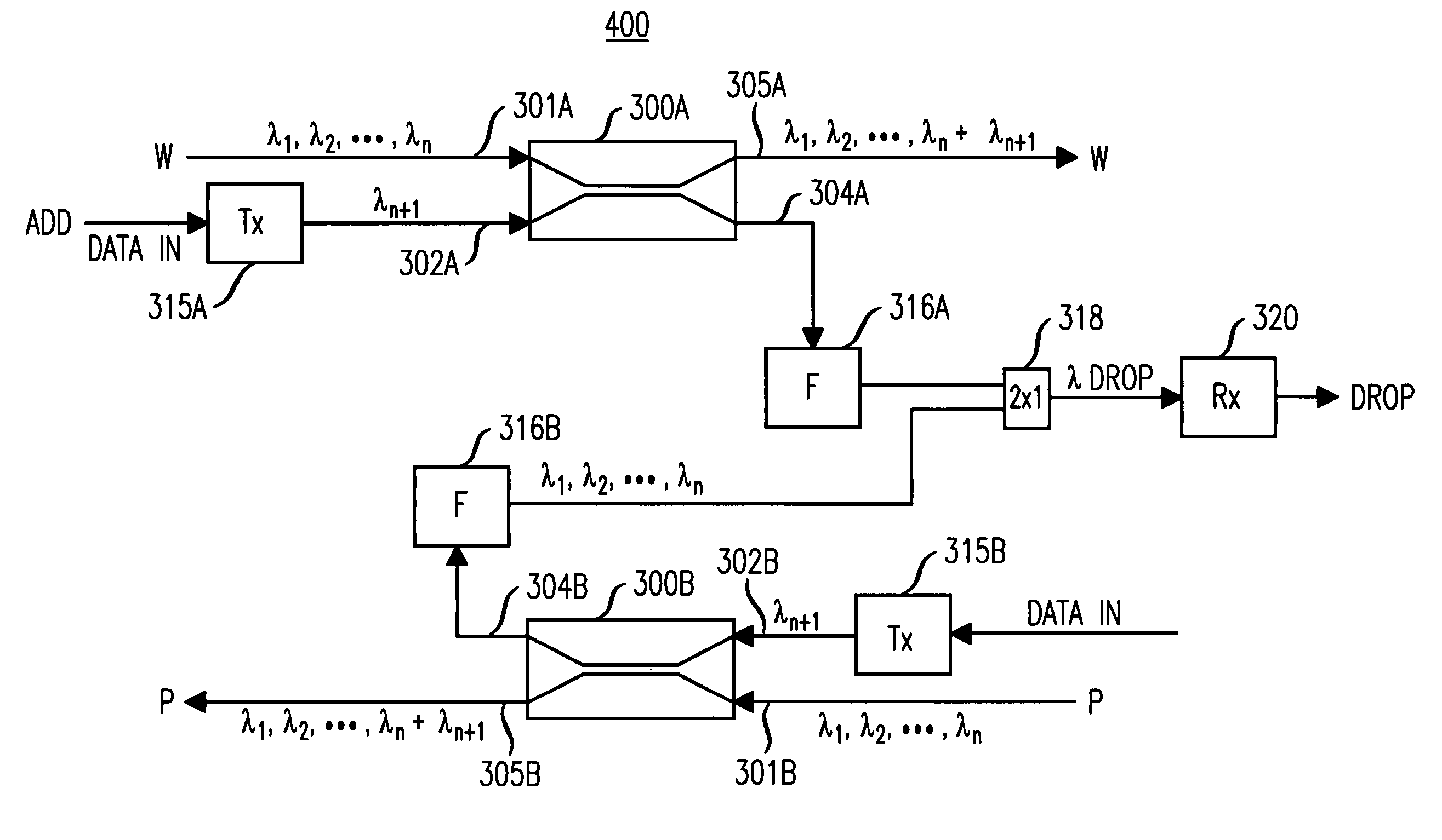
[0009]Cost and optical losses associated with adding and dropping optical channels of a wavelength division multiplexed (WDM) signal in a WDM ring network are substantially reduced over the current art in an add / drop arrangement that uses broadband optical couplers in combination with wavelength conversion and suppression elements. At each node in the WDM ring that includes a broadband optical coupler-based add / drop element, a portion of optical signal power of the entire WDM signal (i.e., all optical channels) is tapped off so that one or more optical channels of particular wavelengths can be dropped at the node. Information (e.g., data) to be added at the node is supplied in an optical channel that is added to the WDM signal via the same broadband coupler. Another portion of optical signal power of the WDM signal (including any added optical channels) passes through the node onto the WDM ring.
[0011]The add / drop arrangement according to the principles of the invention uses components that have low optical losses (e.g., low losses in the drop and through paths), operate over a wide spectral bandwidth (e.g., broadband), and rely on passive rather than active techniques, thus reducing the cost and complexity as compared to prior arrangements. Moreover, problems in the prior add / drop arrangements relating to the cascading of band-narrowing filters are avoided by using broadband couplers for adding and dropping optical channels in a WDM ring.

Problems solved by technology

While such SONET rings perform well, the strong and consistent growth in demand for bandwidth and management of that bandwidth has outgrown the capabilities and capacity of SONET rings.
However, implementation of WDM or DWDM in metropolitan area networks presents a unique set of challenges as compared to long haul network applications.
In addition, flow of traffic, diversity of traffic types, and dynamic changes in traffic levels associated with the adding and dropping of traffic further complicates the management of traffic in the metropolitan area network.
Solving these problems using conventional WDM and DWDM techniques, such as those used in long haul applications, adds significant cost and complexity in the more cost-sensitive metropolitan area environment.
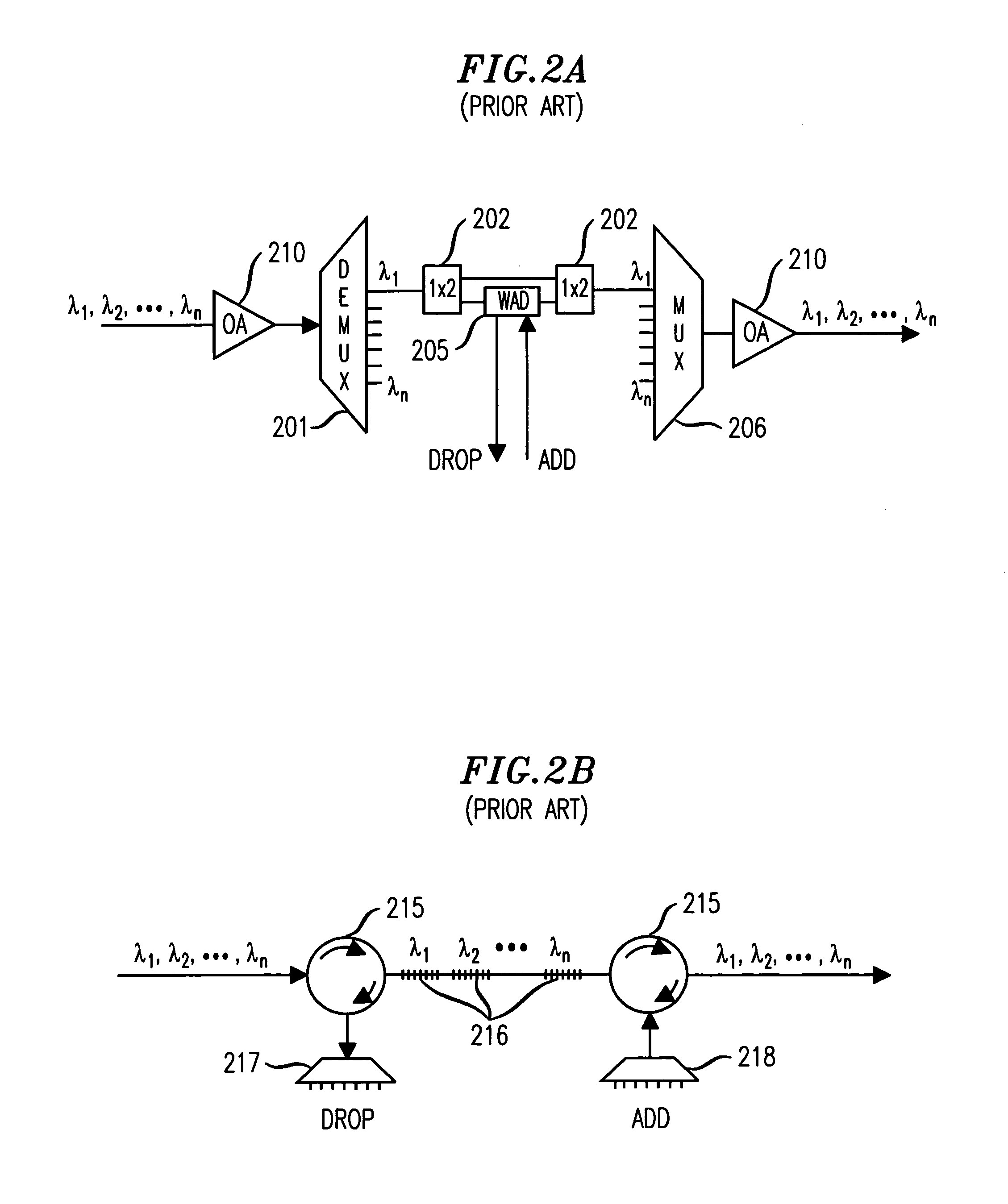
However, these devices have several disadvantages that render them undesirable for practical applications in short haul applications, such as ring networks.
For example, some of these disadvantages include: wavelength dependent loss; power penalties and other transmission impairments due to bandwidth narrowing and group velocity dispersion; limited spectral bandwidth, poor scalability, and high implementation costs.
While the flexibility of bandwidth assignment is a key driver for this application, the cost of providing this capability using straightforward DWDM techniques appears prohibitively expensive for this more cost sensitive environment.

Method used


Image

  • Optical add/drop arrangement for ring networks employing wavelength division multiplexing
  • Optical add/drop arrangement for ring networks employing wavelength division multiplexing
  • Optical add/drop arrangement for ring networks employing wavelength division multiplexing

Examples


example 1

Unidirectional Path-Switched Ring

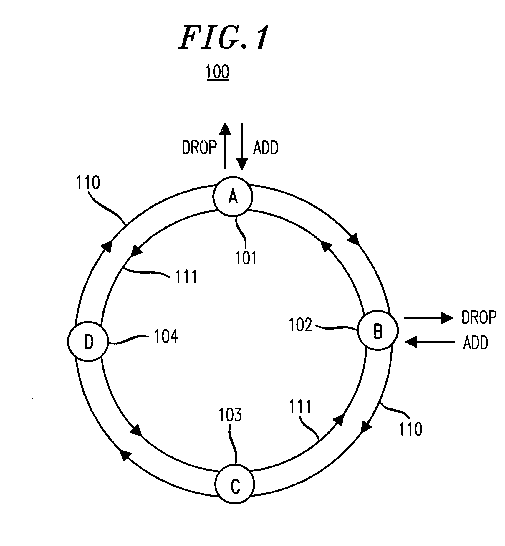
[0051]FIGS. 6A–6D show an exemplary unidirectional path-switched ring (UPSR) 400 in which the principles of the invention may be employed. As shown, UPSR 400 includes nodes 401–403 and a special function node 405, referred hereinafter as termination node 405 for reasons that will be described in more detail below. Nodes 401–403 and termination node 405 are interconnected in a ring configuration via optical fibers 410 and 411, referred hereinafter as working path 410 and protection path 411, respectively. The basic principles of operation of a UPSR are well-known and were briefly summarized in the description accompanying FIG. 1. Nodes 401–403 may each include the broadband coupler-based add / drop arrangement described in the foregoing embodiments (e.g., FIGS. 3 and 4). However, the exemplary scenarios shown in FIGS. 6A–6D illustrate a specific example of communications between nodes 402 and 403 (i.e., nodes B and C). As such, it is assumed that at lea...

example 2

Unidirectional Line-Switched Ring

[0061]The add / drop arrangement according to the principles of the invention may also be advantageously employed in a second type of ring network, the so-called unidirectional line-switched ring (ULSR) network. Again, the basic principles of operation of a ULSR network are well-known. Briefly, nodes in a ULSR communicate by routing signals in the same direction, i.e., unidirectionally, on the working path only. In the event of a node failure, cable cut, or other fault condition, nodes adjacent to the failure location implement so-called “loop back switching” in which signals are routed via the protection path in the direction opposite to that in the working path.

[0062]According to the principles of the invention, WDM signals may be added and dropped in a ULSR using a broadband coupler-based add / drop arrangement. More specifically, FIGS. 9A–9B show an exemplary unidirectional line-switched ring (ULSR) 500 in which the principles of the invention may be...

example 3

2-Fiber Bi-directional Line-Switched Ring

[0070]The add / drop arrangement according to the principles of the invention may also be advantageously employed in another type of ring network, the so-called bi-directional line-switched ring (BLSR) network. As with UPSR and ULSR networks, BLSR networks are well-known in the SONET / SDH domain, e.g., see Bellcore Generic Requirements, GR-1230-CORE, “SONET Bi-directional Line-Switched Ring Equipment Generic Criteria”, December 1996, M. Chow, “Understanding SONET / SDH Standards and Applications”, pp 7–23 to 7–40 (1995), and W. Goralski, “SONET: A Guide to Synchronous Optical Networks”, pp. 342–366(1997), all of which are incorporated by reference herein.

[0071]According to the principles of the invention, WDM signals may be added and dropped in a BLSR using a broadband coupler-based add / drop arrangement at one of more of the nodes in the BLSR. More specifically, FIG. 11 shows an exemplary 2-fiber bi-directional line-switched ring (2F-BLSR) 650 in ...


PUM


Abstract

An add / drop arrangement using broadband optical couplers provides a low-loss, highly flexible add / drop capability for survivable wavelength division multiplexed (WDM) ring networks. At each node in the ring having the broadband optical coupler-based add / drop element, a portion of optical signal power of the entire WDM signal (i.e., all optical channels) is tapped off so that one or more optical channels of particular wavelengths can be dropped at the node. Information (e.g., data) to be added at the node is supplied in an optical channel that is added to the WDM signal via the broadband coupler. Because the add / drop element uses a broadband coupler, another portion of optical signal power of the WDM signal, including any added optical channels, passes through the node onto the ring. Depending on the specific ring topology being used with the broadband coupler-based add / drop arrangement, additional wavelength assignment and handling measures may be required. For example, certain ring topologies may experience interference between optical channels of particular wavelengths due to possible re-circulation of these optical channels beyond the add and drop nodes (e.g., after an optical channel passes its destination node). According to one illustrative embodiment, a node is equipped to perform wavelength conversion and / or wavelength suppression to prevent undesirable re-circulation of optical channels.

Description

TECHNICAL FIELD[0001]This invention relates generally to lightwave communication networks and, more particularly, to adding and dropping signals in wavelength division multiplexed ring networks.BACKGROUND OF THE INVENTION[0002]Optical fiber is becoming the transmission medium of choice for communication networks because of the speed and bandwidth advantages associated with optical transmission. Wavelength division multiplexing (WDM), which combines many optical channels at different wavelengths for simultaneous transmission as a composite optical signal in a single optical fiber, is being used to meet the increasing demands for more speed and bandwidth in optical transmission applications. With recent advances in optical networking technology, system manufacturers are now contemplating dense wavelength division multiplexing (DWDM) systems that include, for example, as many as 80 or more optical channels (i.e., wavelengths) in a single fiber. As such, DWDM optical transport technolog...

Claims


Application Information

Patent Timeline
IPC IPC(8): H04J14/02H04B10/032H04B10/03H04B10/035H04B10/07H04B10/27H04B10/275H04B10/29H04B10/291H04J14/00
CPCH04J14/0204H04J14/0205H04J14/0206H04J14/0213H04J14/0283H04J14/029H04J14/0212
Inventor KOROTKY, STEVEN KENNETHVESELKA, JOHN J.
Owner LUCENT TECH INC
Learn More