
Transponder, including transponder system

a transponder and system technology, applied in the field of transponders including transponders, can solve the problems of insufficient performance margins, few applications of transponders in the various areas, and inability to use high frequency amplification, etc., and achieve the effect of large and small signal properties and easy realisation

Inactive Publication Date: 2005-09-20
VAVIK GEIR MONSEN
View PDF17 Cites 138 Cited by
  • Summary
  • Abstract
  • Description
  • Claims
  • Application Information

AI Technical Summary

Benefits of technology

The present invention is a two-way signal booster that can work with or without a galvanic connection. It can also act as an amplifier for both small and large signals. The invention is easy to realize at high frequencies like mm frequency bands. In a communication system, the invention allows for low levels on lines or in radio systems by using a sufficient number of transponders with close spacing. This reduces the need for authority licensing requirements.

Problems solved by technology

The patent text discusses the need for a new technology that can amplify signals in a simple and cost-effective way, without reducing bandwidth or requiring additional infrastructure. The text also describes the need for a new technology to address issues in power line surveillance and communication, such as limited range and high costs. The technical problem is to develop an inexpensive transponder technology that can amplify signals in both directions, without reducing the need for expensive and complicated infrastructure.

Method used


Image

  • Transponder, including transponder system
  • Transponder, including transponder system
  • Transponder, including transponder system

Examples


Embodiment Construction

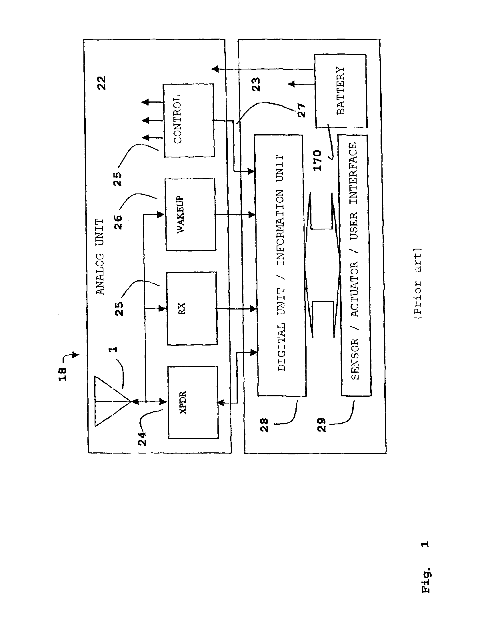
[0065]In FIG. 1 is shown a typical transponder device 18 consisting of an analogue 22 and a digital 23 unit. The analogue part has an antenna 1 and a radio frequency transponder 24. It is often designed to include a down link receiver 25 and a wake up receiver 26 as well as a control unit 25. When the digital part is included in the transponder device 18 it will consist of an information unit 28 normally combined with an interface 29. The transponder device 18 also consists of a power supply most commonly made up of a battery 170.

[0066]The most important part of the transponder device 18 is the transponder 24 for up link. The down link information receiver 25 is either a separate part of the transponder device 18 or is partly integrated with the wake up receiver 26. The digital unit 23 information device 28 identifies the transponder device 18 and the digital unit may also posses abilities of processing information as well as perform control of functions in the analogue unit 22 thro...


PUM


Abstract

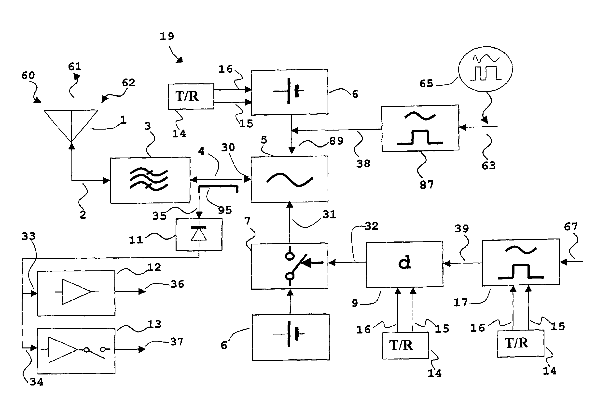
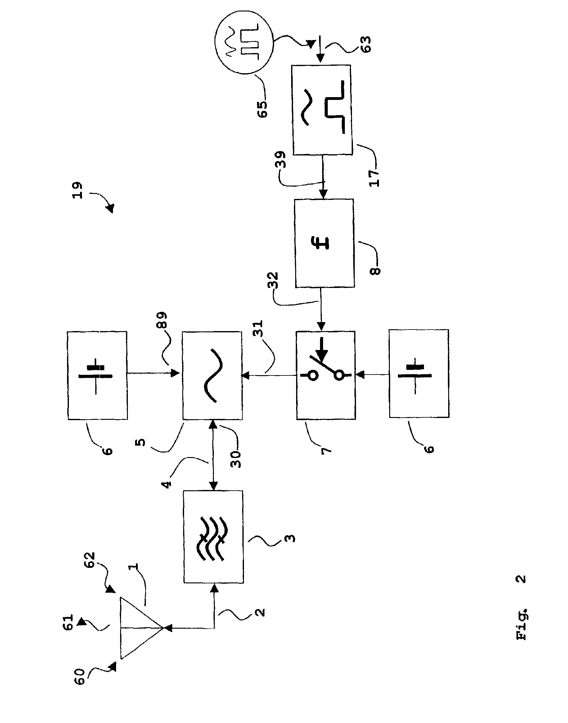
In a transponder (19) for amplification of a received signal (60) into an antenna (1), to a signal (61) for retransmission, and where the retransmitted signal (61) possibly may have information superimposed, a quenched oscillator (5) is incorporated as amplifying element. The oscillator (5) is preferably of superregenerative type and exhibits negative resistance (30) for the received signal (60). Transponders according to the present invention may be introduced as system elements in a wireless or wire based network to work as intelligent or unintelligent connections in the network. The transponders can also be used in positioning systems.

Description


Claims


Application Information

Patent Timeline
Owner VAVIK GEIR MONSEN
Learn More