Hydraulic stroke measuring system

Inactive Publication Date: 2005-09-20
JOHNSON CLIFFORD C
View PDF18 Cites 5 Cited by
  • Summary
  • Abstract
  • Description
  • Claims
  • Application Information

AI Technical Summary

Benefits of technology

[0010]In view of the foregoing disadvantages inherent in the known types of cylinder systems now present in the prior art, the present invention provides a new hydraulic stroke measuring system construction wherein the same can be utilized for accurately determining the cylinder rod position within a hydraulic cylinder.
[0016]A second object is to provide a hydraulic stroke measuring system for accurately determining the cylinder rod position within a hydraulic cylinder.
[0018]An additional object is to provide a hydraulic stroke measuring system that efficiently informs the user of the exact position of the cylinder shaft.
[0019]A further object is to provide a hydraulic stroke measuring system that reassures a user that a piece of equipment is being operated properly.
[0020]Another object is to provide a hydraulic stroke measuring system that is comprised of a simple construction.

Problems solved by technology

The main problem with conventional hydraulic cylinders is the user cannot determine the exact position of the cylinder rod.
A further problem with conventional hydraulic cylinders is that equipment dependent upon the hydraulic cylinders are sometimes operated at an incorrect depth or height.
For example, if a planter is not adequately lowered so that the discs are penetrating the ground surface at a desired depth, the seeds will not be properly planted resulting in the loss of that crop.
While these devices may be suitable for the particular purpose to which they address, they are not as suitable for accurately determining the cylinder rod position within a hydraulic cylinder.
Conventional hydraulic cylinders do not provide a system for indicating the exact position of the cylinder rod.

Method used


Image

  • Hydraulic stroke measuring system
  • Hydraulic stroke measuring system
  • Hydraulic stroke measuring system

Examples


Embodiment Construction

A. Overview

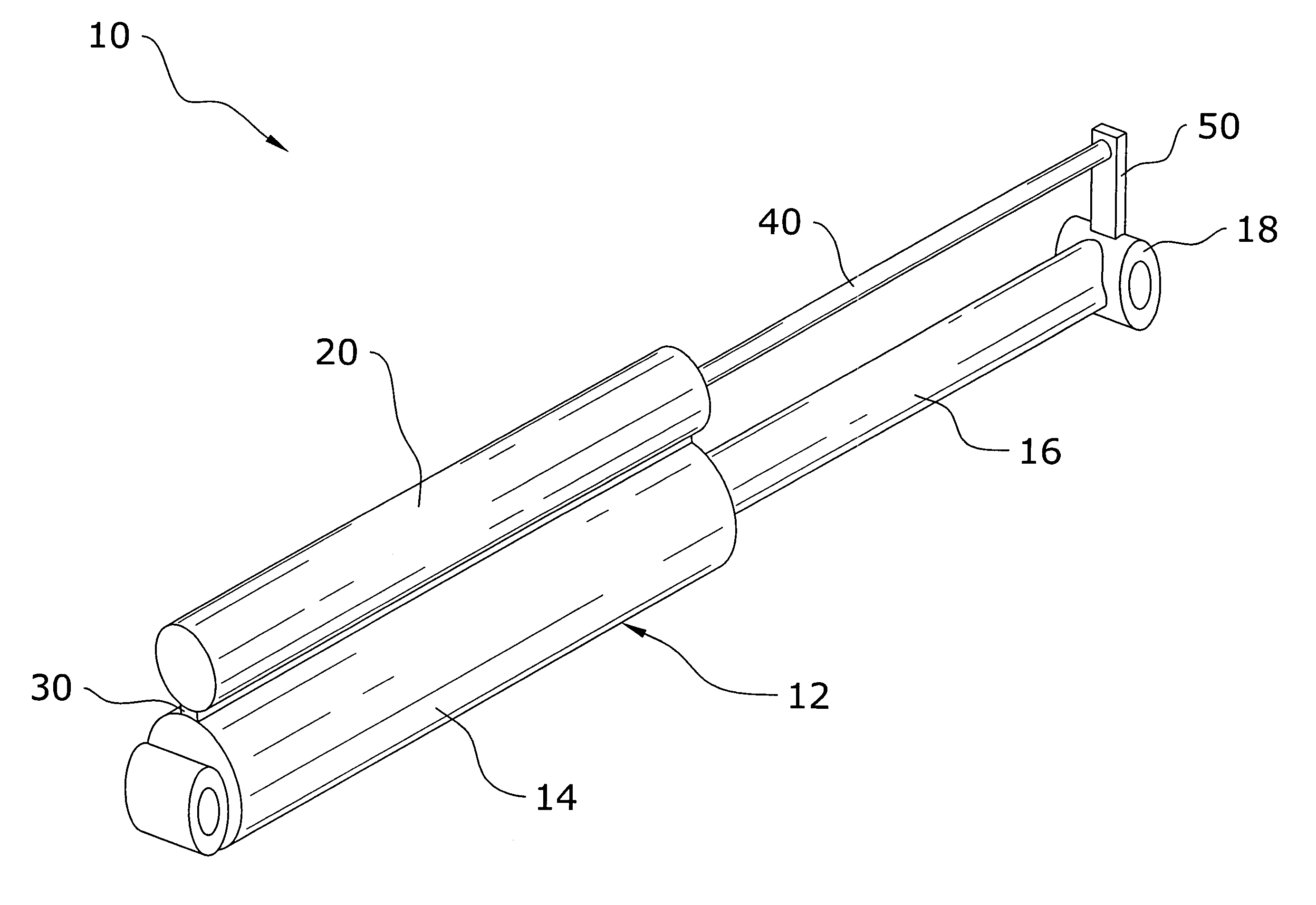
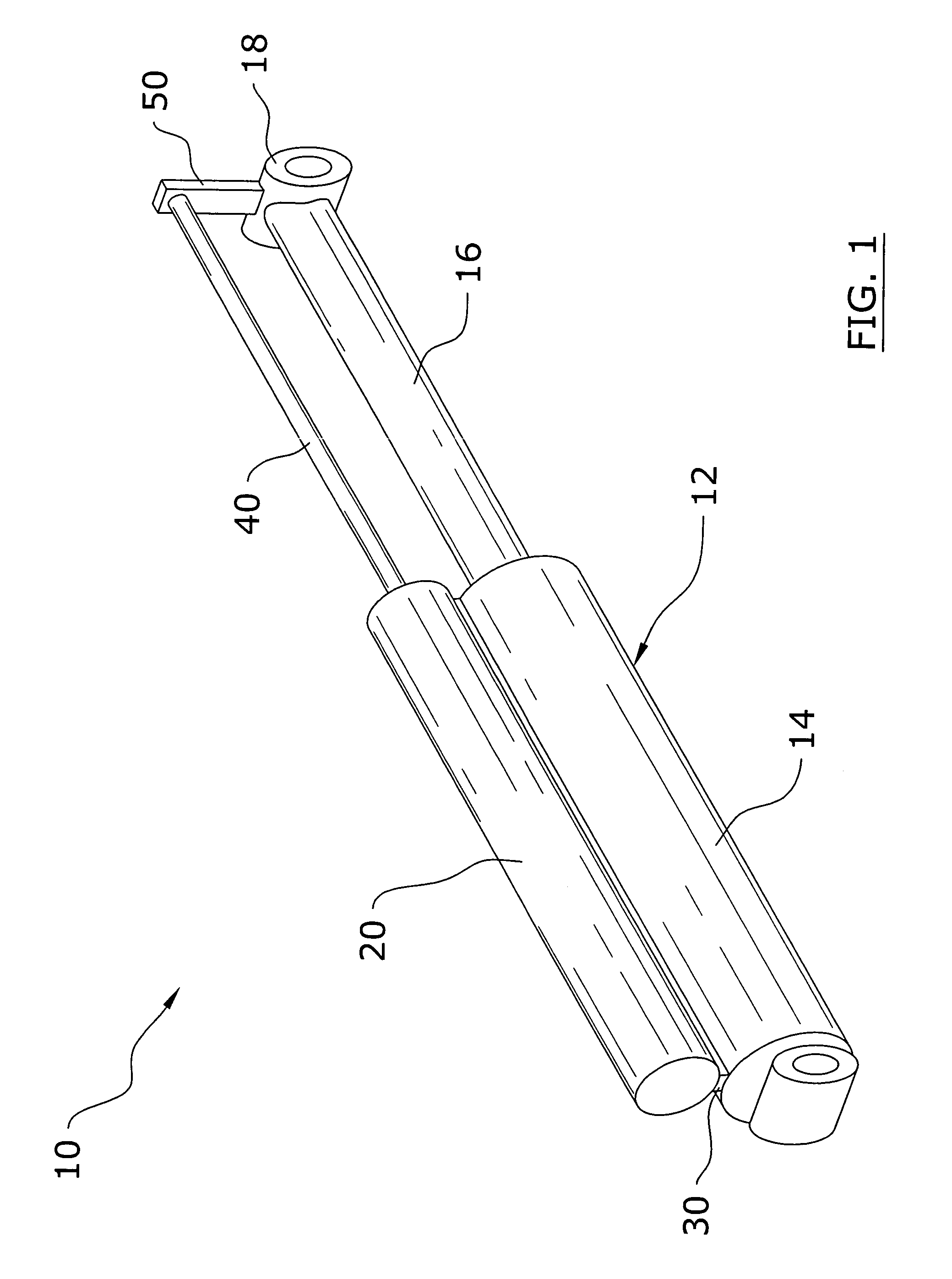
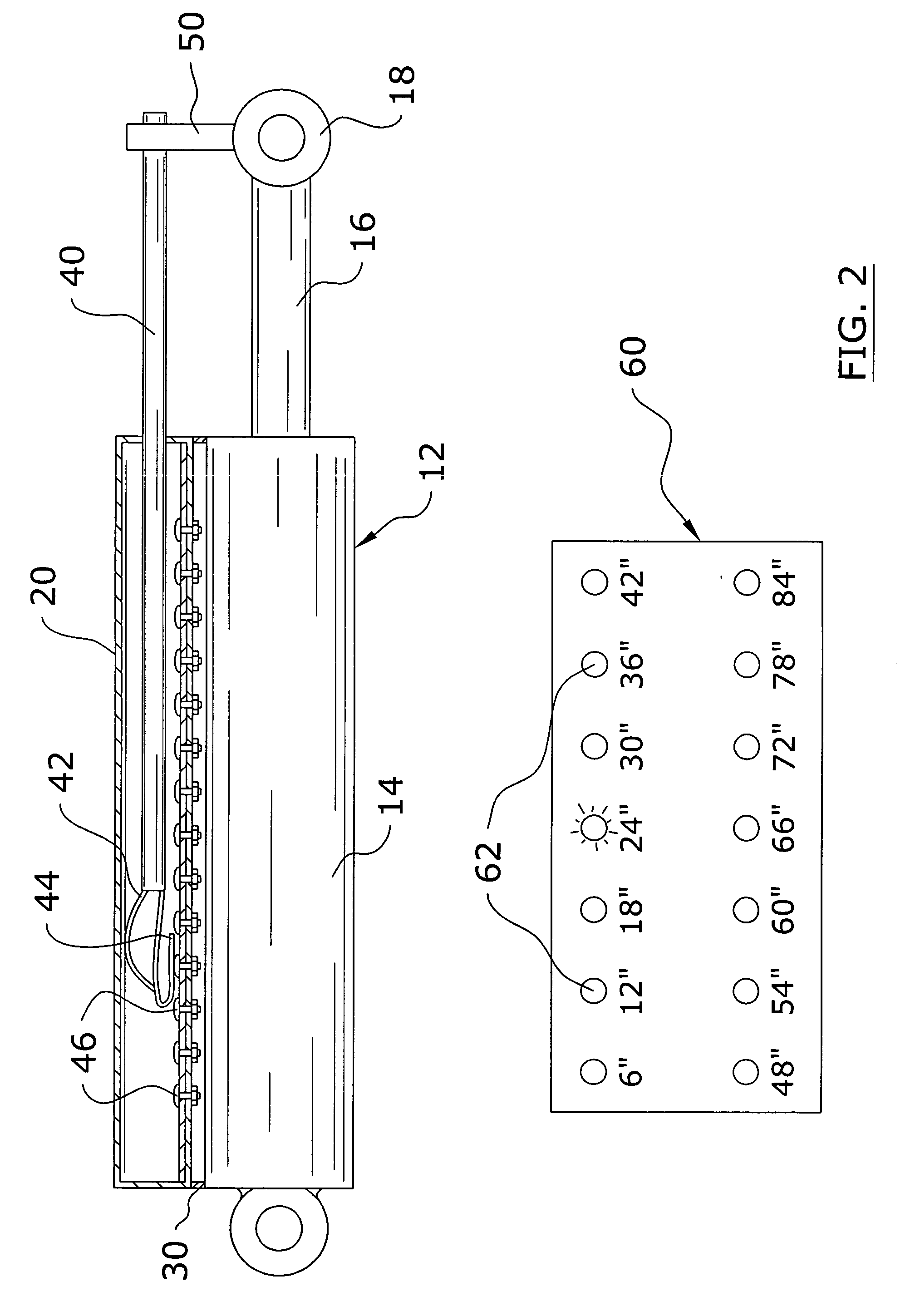
[0031]Turning now descriptively to the drawings, in which similar reference characters denote similar elements throughout the several views, FIGS. 1 through 7 illustrate a hydraulic stroke measuring system 10, which comprises a measurement shaft slidably positioned within a housing unit 20, a shaft bracket 50 attachable between the measurement shaft and a cylinder shaft 16 of a hydraulic cylinder 12, a plurality of contact members 46 within the housing unit 20, a main contact 44 attached to the measurement shaft for selectively engaging one or more of the contact members 46, and a plurality of display lights 62 electrically connected to the contact members 46. The display lights 62 illuminate when the main contact 44 engages the corresponding contact members 46.

B. Measurement Unit

[0032]The measurement unit is preferably attached to a cylinder shaft 16 of a hydraulic cylinder 12 by a housing bracket 30. However, the measurement unit may be attached to various other structu...


PUM


Abstract

A hydraulic stroke measuring system for accurately determining the cylinder rod position within a hydraulic cylinder. The hydraulic stroke measuring system includes a measurement shaft slidably positioned within a housing unit, a shaft bracket attachable between the measurement shaft and a cylinder shaft of a hydraulic cylinder, a plurality of contact members within the housing unit, a main contact attached to the measurement shaft for selectively engaging one or more of the contact members, and a plurality of display lights electrically connected to the contact members. The display lights illuminate when the main contact engages the corresponding contact members.

Description

CROSS REFERENCE TO RELATED APPLICATIONS[0001]Not applicable to this application.STATEMENT REGARDING FEDERALLY SPONSORED RESEARCH OR DEVELOPMENT[0002]Not applicable to this application.BACKGROUND OF THE INVENTION[0003]1. Field of the Invention[0004]The present invention relates generally to hydraulic cylinders and more specifically it relates to a hydraulic stroke measuring system for accurately determining the cylinder rod position within a hydraulic cylinder.[0005]2. Description of the Related Art[0006]Hydraulic cylinders have been in use within agriculture, construction and other industries for years. A conventional hydraulic cylinder has a cylinder housing and a cylinder shaft slidably extending from the cylinder housing. Pressurized hydraulic fluid is input into the cylinder housing to force the cylinder rod inwardly or outwardly with respect to the cylinder housing.[0007]The main problem with conventional hydraulic cylinders is the user cannot determine the exact position of th...

Claims


Application Information

Patent Timeline
IPC IPC(8): G08B21/00F15B15/28
CPCF15B15/2807
Inventor JOHNSON, CLIFFORD C.
Owner JOHNSON CLIFFORD C
Why Eureka
Try Eureka