Guide rails for pull-out drawer/equipment
a technology for pull-out drawers and guide rails, which is applied in the direction of drawers, furniture parts, domestic applications, etc., can solve the problems of very large reduction in strength and rigidity
- Summary
- Abstract
- Description
- Claims
- Application Information
AI Technical Summary
Benefits of technology
Problems solved by technology
Method used
Image
Examples
first embodiment
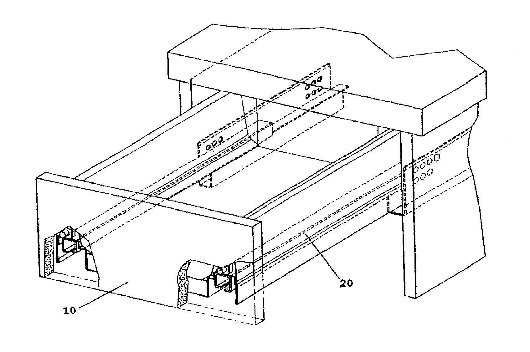
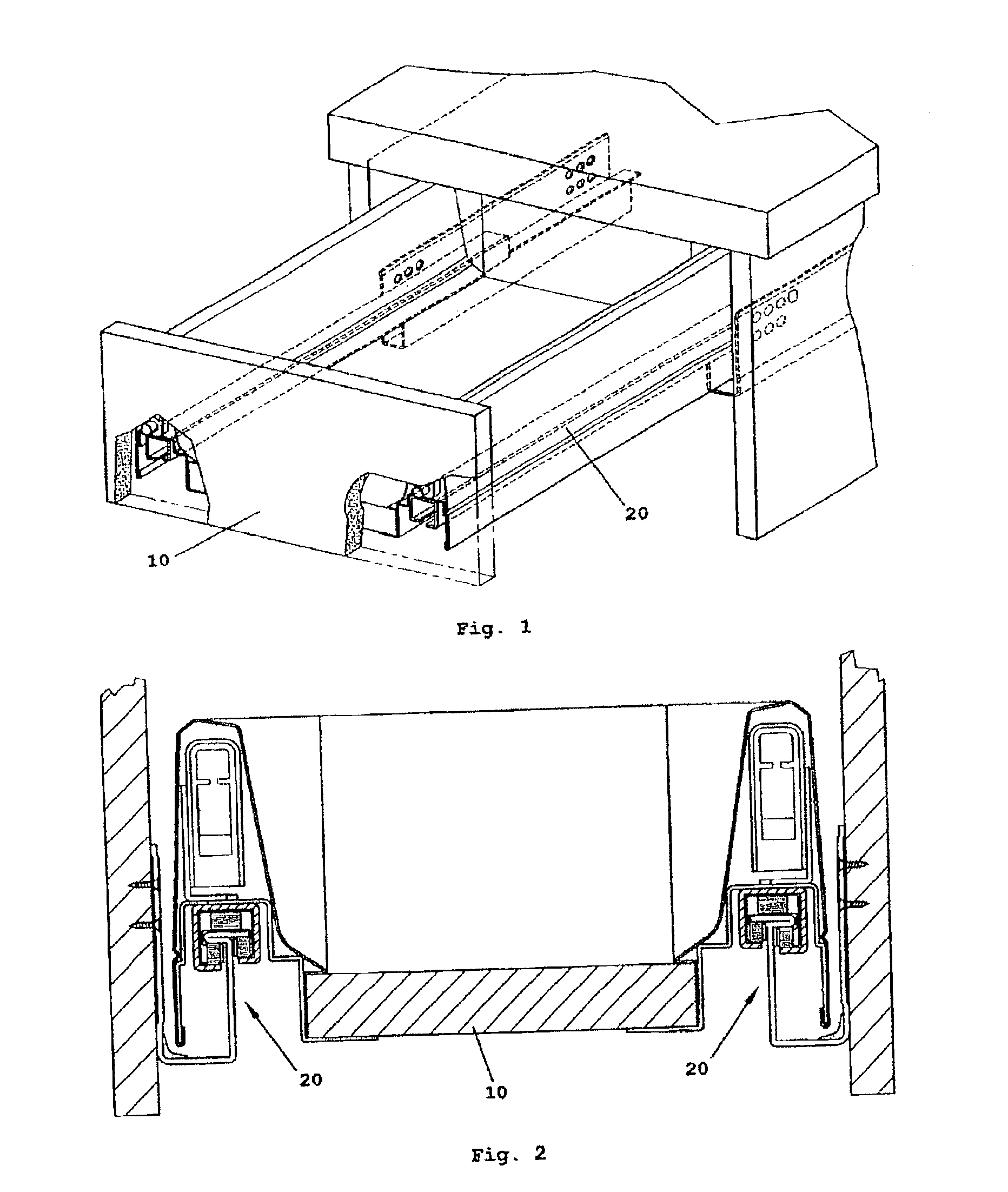
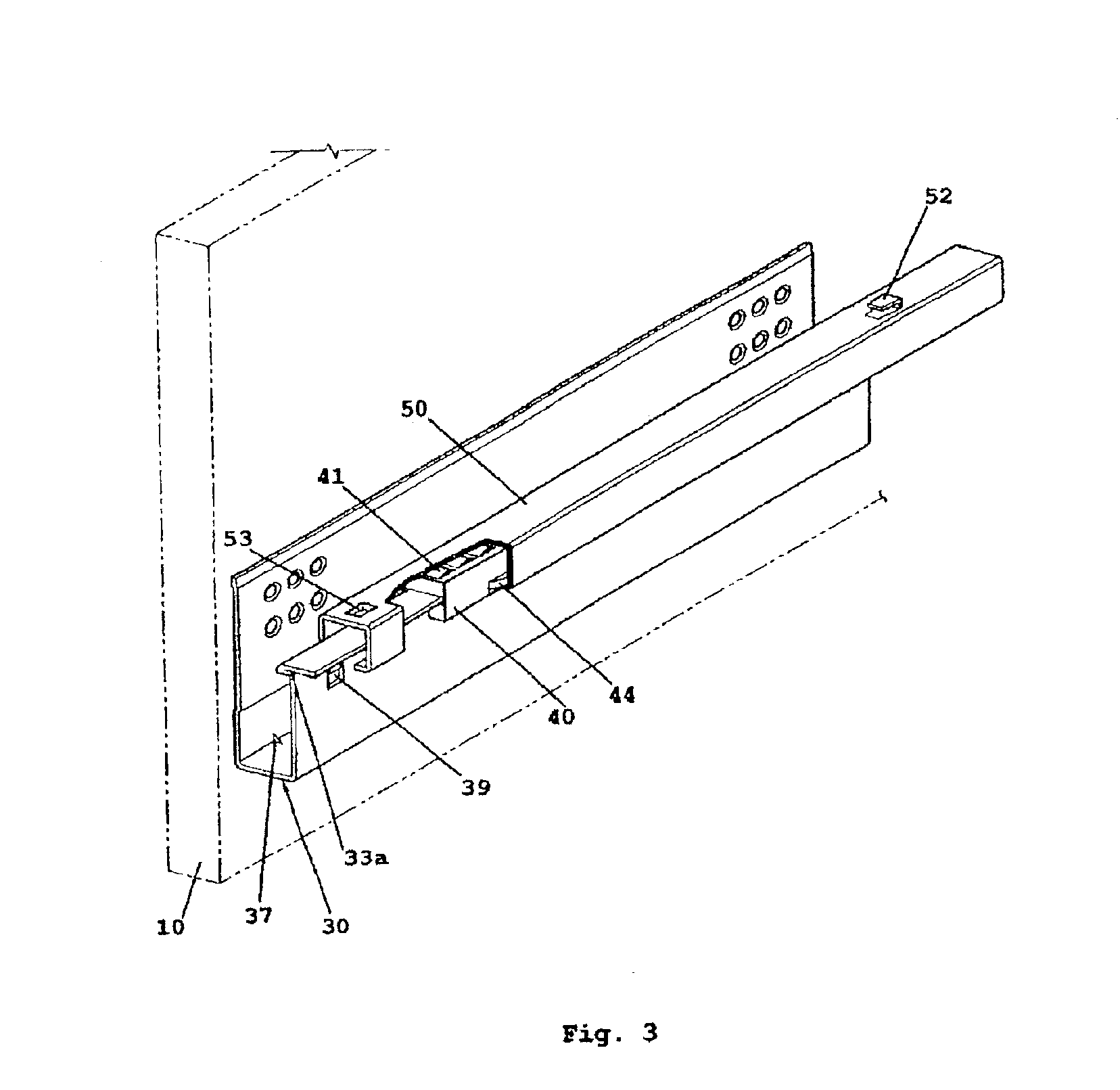
[0052]Referring to FIG. 1, a slide rail assembly 20 is installed at each of the two sides of a drawer or slid able storage compartment / equipment 10. The sectional view of the drawer assembly, illustrated in FIG. 2, shows each slide rail comprising of a fixed support member 30; a roller housing 40; and a pull-out guide 50. FIG. 3 shows a perspective view of the slide rail assembly.
[0053]The fixed support member 30 is formed from a sheet metal into a substantially U shaped section. The longer flange 31 of the U has a multitude of holes 32 for mounting this support member 30 onto the inner side of a cabinet, for example, where a drawer or piece of equipment is to be slidably installed into. The other flange 33 is shorter and substantially parallel to flange 31. The long edge of flange 33 is formed into a T shaped rail 33a, with the horizontal legs 34, 35 of the T being substantially equal in width from either side of the vertical leg or web 36.
[0054]The centre part of the U-section is...
second embodiment
[0065]FIG. 6 shows a sliding guide 20a. This sliding guide 20a comprises of a fixed support bracket 110; a fixed sliding guide 120; a lower roller housing 40a; a pull-out slide rail 140; an upper roller housing 40b; and a pull-out guide 150. FIG. 7 illustrates a sectional view of this embodiment, while FIG. 8 shows a perspective view of an assembled slide rail 20a.
[0066]As shown in FIG. 9a, the fixed support bracket 110 is formed from a sheet metal into a substantially L-section. The vertical flange 111 has a multitude of holes 112 for fixing to the side of a cabinet or chassis into which a drawer or equipment is to be installed in. As described earlier for flange 31, stepped edges 113 are formed on flange 111 for increasing its rigidity. Similarly, notches 114 are formed at the bent edge for increasing the rigidity and load capacity of this bracket.
[0067]On the horizontal flange 115 of bracket 110 is attached a fixed guide 120. This guide 120 is formed from a sheet metal into an o...
third embodiment
[0074]FIG. 10 shows a sliding rail 20b in which the rail is mounted below the drawer rather than at the sides. With this arrangement, the vertical height of the slide assembly 20b is preferably kept low, so that the available height in the drawer is not sacrificed. This assembly 20b comprises a fixed support bracket 30a; roller housing 40c; intermediate pull-out guide 160; roller housing 170; and pull-out guide 180. FIG. 11 is a sectional view of this embodiment, whilst FIG. 12 is a perspective view of slide assembly 20b.
[0075]As shown in FIG. 13a, support bracket 30a is similar in construction with bracket 30. However, the heights of vertical flanges 31a, 31b are shorter and are kept to the minimum possible and is formed from a sheet metal. The T-rail 33a is also similar to that described for the previous embodiments.
[0076]FIG. 13b shows the roller housing 40c which is similar to the roller housing 40, 40a or 40b described above. With similar function, housing 40c fits onto the T-...
PUM
 Abstract
Description
Claims
Application Information
 - R&D
- Intellectual Property
- Life Sciences
- Materials
- Tech Scout
- Unparalleled Data Quality
- Higher Quality Content
- 60% Fewer Hallucinations
Browse by: Latest US Patents, China's latest patents, Technical Efficacy Thesaurus, Application Domain, Technology Topic, Popular Technical Reports.
© 2025 PatSnap. All rights reserved.Legal|Privacy policy|Modern Slavery Act Transparency Statement|Sitemap|About US| Contact US: help@patsnap.com


