
Control arrangement for a vehicle

a technology for controlling devices and vehicles, applied in mechanical control devices, manual control with single controlling member, instruments, etc., can solve problems such as unfavorable use and crowded areas, and achieve the effect of improving ergonomics and driving safety

Inactive Publication Date: 2005-09-20
SCANIA CV AB
View PDF28 Cites 14 Cited by
  • Summary
  • Abstract
  • Description
  • Claims
  • Application Information

AI Technical Summary

Benefits of technology

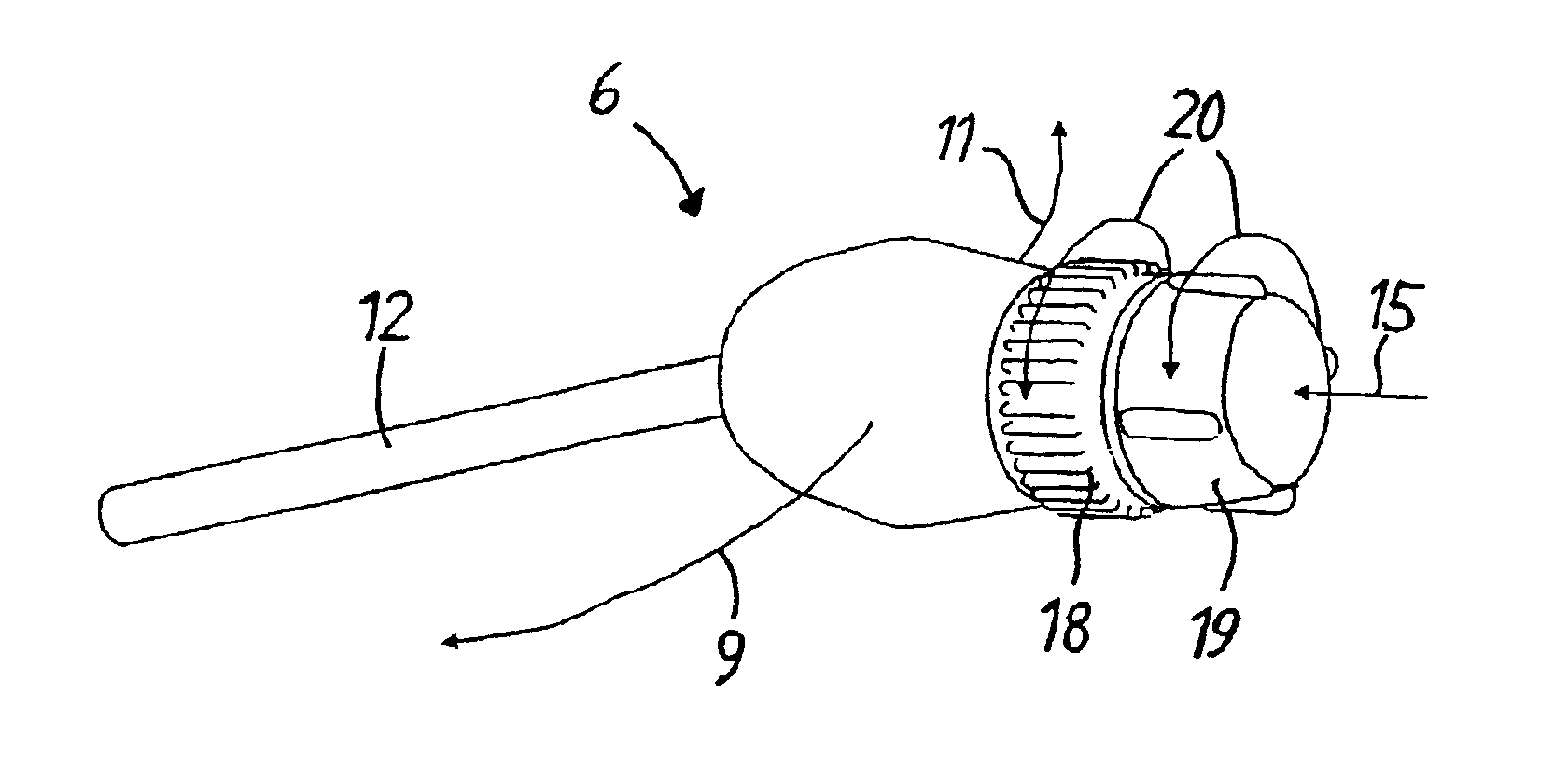
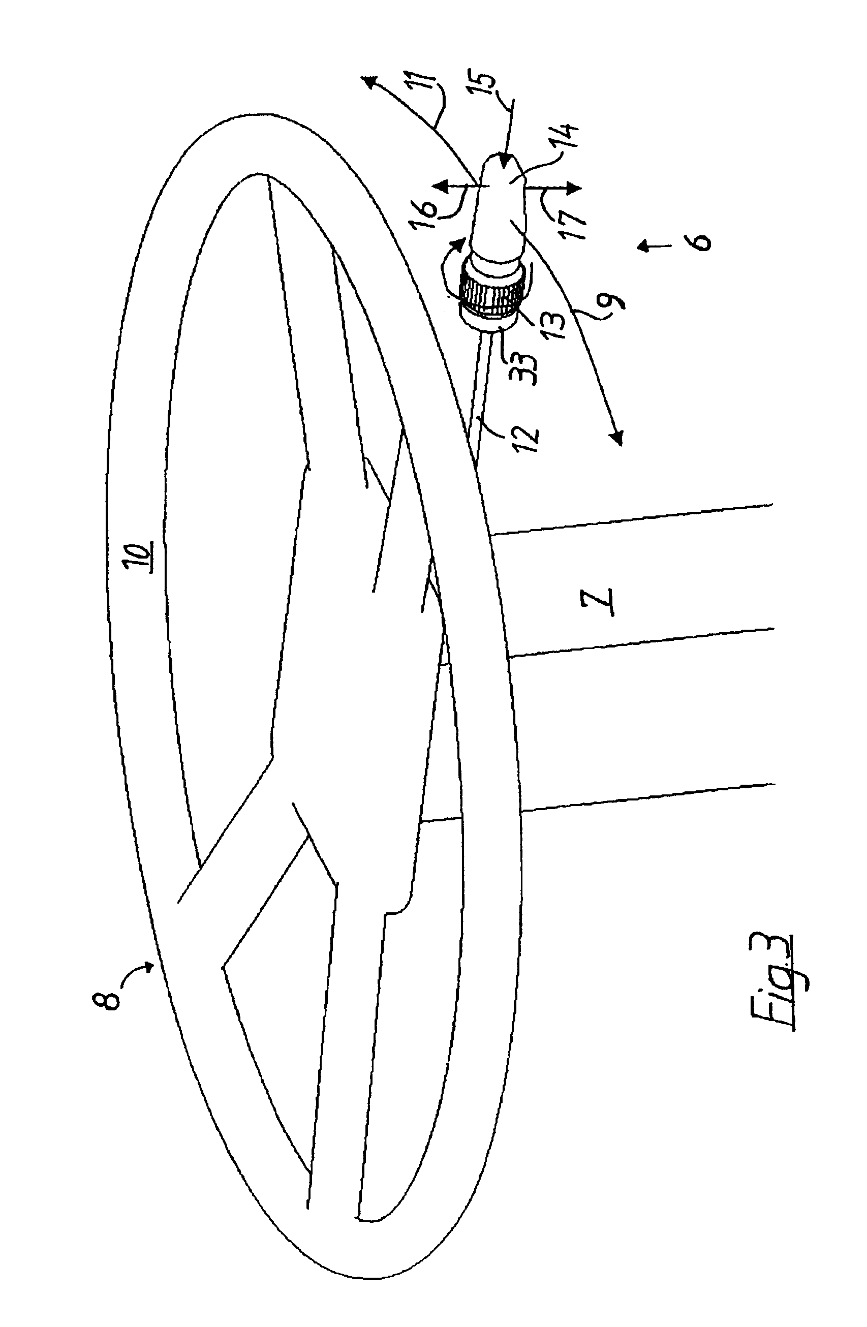
[0006]The object of the invention is to eliminate the above noted disadvantages and provide a new multi-functional control device which replaces both the gear lever and the retarder lever, resulting in greater driving safety and better ergonomics for the driver. This is achieved with an arrangement which is operable via one lever at the steering wheel.
[0008]Having the combined gear and retarder lever located at the steering wheel improves the driver's driving situation in terms of safer gearchange procedure. The lever is substantially closer to the steering wheel than the conventional gear lever location on the engine tunnel, thereby making it easier for the driver to maintain concentration on the road during gearchange operations. Gear changing can be carried out without the driver having to take a hand off the steering wheel.
[0009]Valuable space in the vehicle's cab is also gained by removing the gear lever from the engine tunnel. This makes it easier for the driver to move from the driving seat to other spaces in the cab, e.g. the bunk.
[0010]The combined gear and retarder lever improves the ergonomics for the driver. As previously mentioned, the retarder lever on today's vehicles is often situated such that the driver has to reach for it when he wishes to use it. Making the control more readily accessible makes the retarder easier to use and increased use of this function is therefore to be expected.
[0011]Having a lever for two functions causes no conflict as regards the location of the lever such as would be the case if separate gear and retarder levers were situated at the steering wheel. Hence the lever can be situated at the best possible location from the ergonomic and practical point of view. A further advantage is that only one lever housing for the two functions has to be mounted on the steering column.

Problems solved by technology

This means that the driver has to take a hand off the steering wheel when operating the gear lever.
This movement may be perceived as inconvenient and difficult, thereby contributing to the retarder not being used to the desirable extent.
A problem in shifting a number of controls and levers to the steering wheel, where for example flasher and windscreen wiper levers are already situated, is that the area becomes crowded and hence not readily accessible.

Method used


Image

  • Control arrangement for a vehicle
  • Control arrangement for a vehicle
  • Control arrangement for a vehicle

Examples


Embodiment Construction

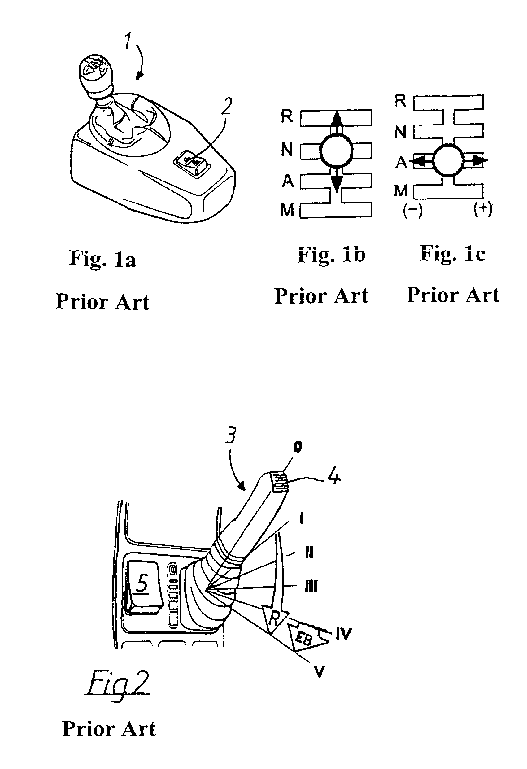
[0017]The known gear lever (1) depicted in FIG. 1 is connected to a semi-automatic (so-called opticruise) gearbox whereby a computer-controlled system makes automatic gearchanging possible with a manual gearbox. Gear changes can be effected fully automatically by the computer or, if so desired, manually by the driver. The lever (1) is situated on the vehicle's engine tunnel beside the driving seat.

[0018]The driver selects for himself the driving program he wishes to use. The driving programs available are manual (M), automatic (A), neutral (N) and reverse (R). The desired driving program is set by the driver moving the lever (1) in the longitudinal direction of the vehicle (FIG. 1b) to the appropriate position (R, N, A or M). To change gear up or down, the lever is moved to the left or right respectively transversely to the longitudinal direction of the vehicle (FIG. 1c). Gear changing is possible irrespective of the driving program set (R, N, A or M).

[0019]A so-called bill button (...


PUM


Abstract

A control device in a vehicle, which control device is connected to, and is for operating, a semi-automatic gearbox, can be set in various gearchange function positions and can, in at least one gearchange function position for traveling forwards, be operated for gear changing. The control device is also connected to, and is for operating, a supplementary brake. This control device replaces both the gear lever and the supplementary brake lever, resulting in increased driving safety and better ergonomics for the driver.

Description

BACKGROUND OF THE INVENTION[0001]The present invention relates to a control device in a vehicle.STATE OF THE ART[0002]Developing the driver's environment in a vehicle involves endeavouring to render all controls and levers as readily accessible to the driver as possible. The more the driver can concentrate on the road, the safer the performance of the vehicle will be. A natural step is therefore to try to situate as many controls and functions as possible at or near the steering wheel.[0003]One of the controls which the driver frequently uses is the gear lever. A gear lever for a semi-automatic gearbox is known from SE 462 246. The lever can be moved in the longitudinal direction of the vehicle for setting various functional positions. The positions are for manual gear selection (M), automatic gear selection (A), neutral (N) and reverse (R). In positions M and A the lever can be moved perpendicular to the longitudinal direction of the vehicle in order to change gear. The lever is co...

Claims


Application Information

Patent Timeline
Patent Type & Authority Patents(United States)
IPC IPC(8): B60K20/06B60T7/02B60T7/10F16H59/02G05G9/047G05G9/00B60K20/02G05G1/01
CPCB60K20/06B60K37/06B60T7/10F16H59/0204G05G9/047B60K2350/102G05G2009/04777G05G2009/04781F16H2059/0239F16H2059/081F16H2059/0247B60K2370/126
Inventor COLLING, MORGANALGESTEN, DAVID
Owner SCANIA CV AB
Learn More