
Clip for mounting weatherstrip

a technology for mounting clips and weatherstrips, which is applied in the direction of snap fasteners, buckles, transportation and packaging, etc., can solve the problems of not being able to use clips, not having enough heat resistance for synthetic resins, and being difficult to meet the demand for reducing the number of parts to simplify the management of parts, so as to increase the ability of window frame side members to bend

Inactive Publication Date: 2005-09-20
NIFCO INC +1
View PDF17 Cites 8 Cited by
  • Summary
  • Abstract
  • Description
  • Claims
  • Application Information

AI Technical Summary

Benefits of technology

[0008]With this configuration, the weatherstrip side member and the window frame side member can be formed separately, and it is easy to combine them. Therefore, it is possible to change a material of the two members without complicating an assembling process.
[0012]According to the fourth aspect, engagement means having a claw provided on one of the engagement piece and holding portion and a hole provided on the other is provided between the engagement piece and the holding portion, so that both can be easily combined.
[0013]According to the fifth aspect, the claws provided between the engagement piece and the holding portion are provided at multiple positions in a moving direction when the engagement piece slides relative to the holding portion. With this configuration, the claws can correspond easily to a difference in sizes between the engagement position for the weatherstrip and the attachment position for the window frame.
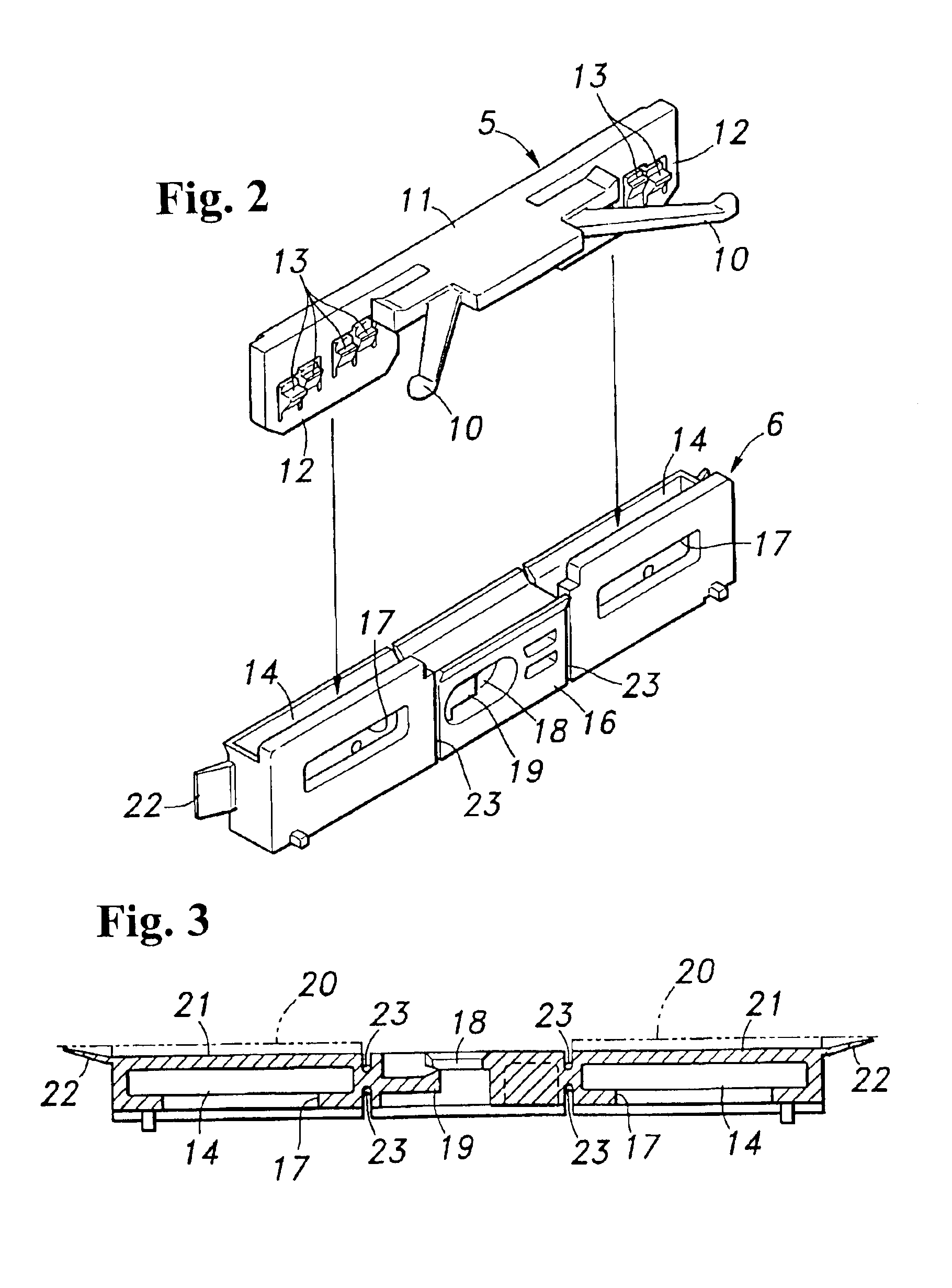
[0015]According to the seventh aspect, a groove perpendicular to the longitudinal direction of the window frame is provided on at least one of the surfaces of the window frame side member parallel to the window frame surface. With this configuration, since it is possible to increase an ability of the window frame side member to bend in the longitudinal direction, it is possible to secure close attachment of the window frame side member relative to the window frame surface.

Problems solved by technology

However, in general, a synthetic resin does not have enough heat resistance to withstand heat for curing the adhesive.
Therefore, it is not possible to use a clip using the T stud and a clip using the adhesive together, and it is difficult to satisfy a demand for reducing the number of parts to simplify part management.

Method used


Image

  • Clip for mounting weatherstrip
  • Clip for mounting weatherstrip
  • Clip for mounting weatherstrip

Examples


Embodiment Construction

[0019]Hereunder, the present invention will be described in detail with reference to the accompanying drawings.

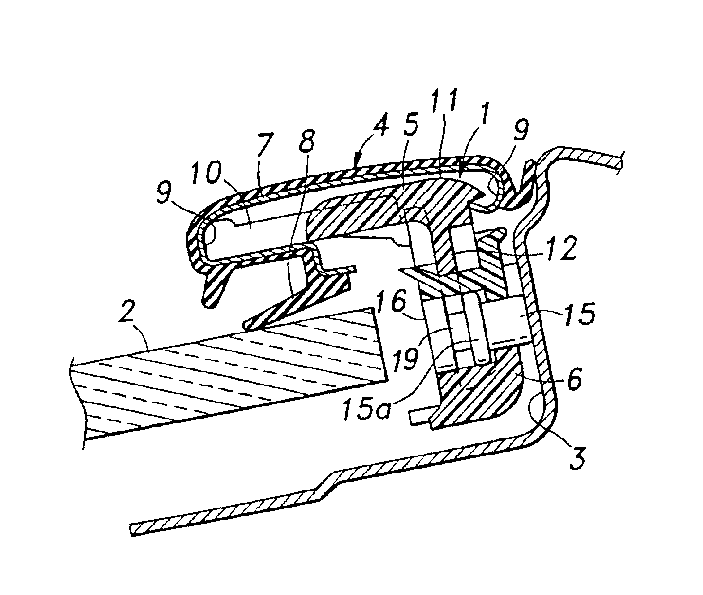
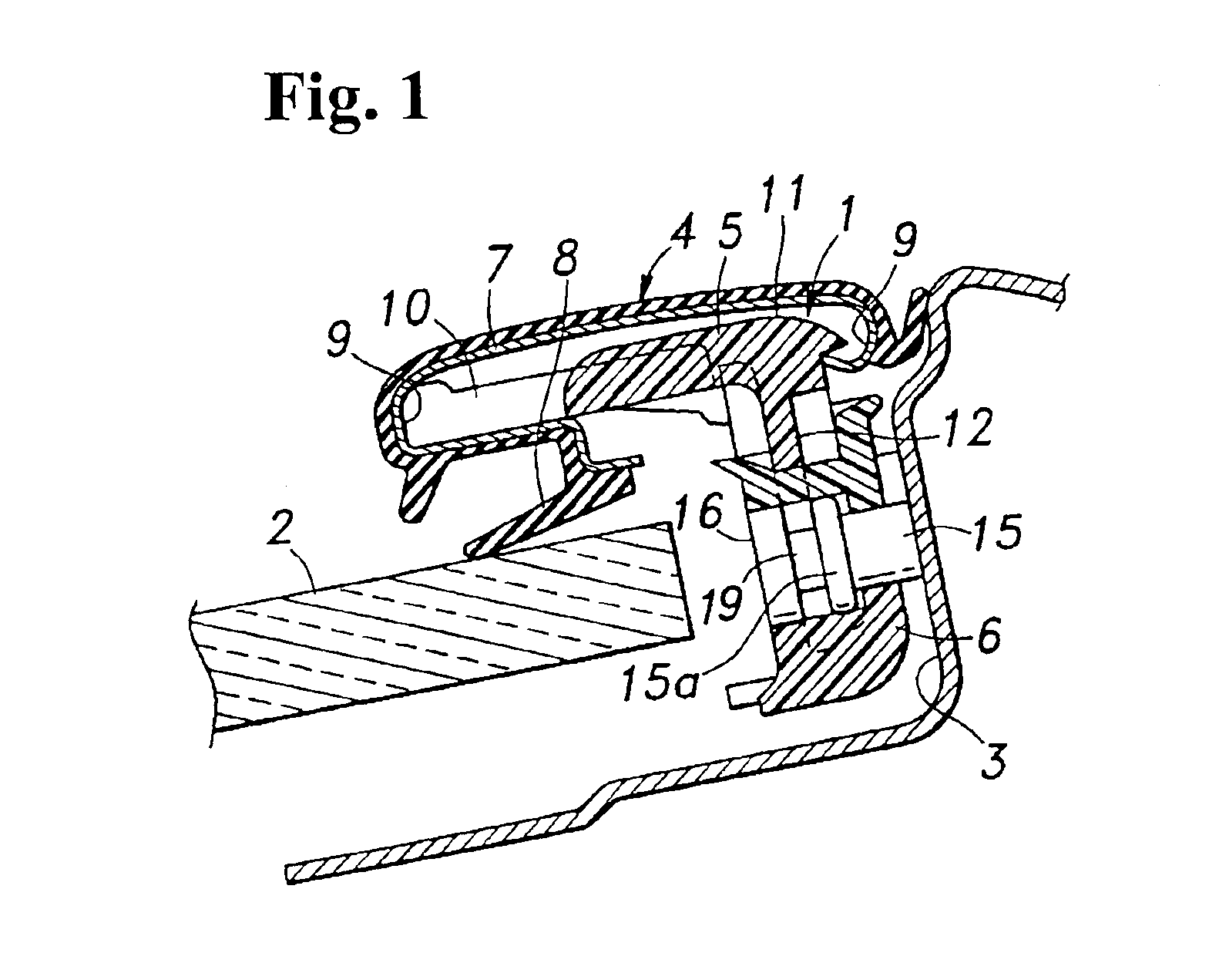
[0020]FIGS. 1-3 show a clip for mounting a weatherstrip according to the present invention. A clip 1 is constructed of two members, i.e. a weatherstrip side member 5 and a window frame side member 6. The clip 1 is used for mounting a weatherstrip 4 as a sealing and decoration member to a position between a side end surface of a front window shield 2 of an automobile and a window frame surface 3 of a front pillar opposite to the side end surface of the front window shield 2.

[0021]As shown in FIG. 1, in the weatherstrip 4 mounted with the clip 1, a seal lip 8 made of an elastic material is molded relative to a core metal 7 formed of metal with a roughly C-shape cross section. A weatherstrip side member 5 to be directly attached to the weatherstrip 4 includes: a pair of arms 10 having a V-shape and engaging one of hemming portions 9 at both sides of the weatherstrip 4 in a wid...


PUM


Abstract

A clip for mounting a weatherstrip between an end side of a window and a window frame includes: a weatherstrip side member having arms for engaging the weatherstrip and tabular engagement pieces extending from a base portion of the arms; and a window frame side member including box-shape holding portions for allowing the tabular engagement pieces to slide therein and an attachment device, i.e. T stud attachment portion and a double-sided tape, for attaching to the window frame. An engagement device is provided between the engagement pieces and the holding portions, and is formed of claws provided on one of the engagement pieces and holding portions and holes provided on the other. The weatherstrip side member and the window frame side member can be separately formed, and easily combined.

Description

BACKGROUND OF THE INVENTION AND RELATED ART STATEMENT[0001]The present invention relates to a clip for mounting a weatherstrip in order to attach the weatherstrip between an end surface of a window and a surface of a window frame opposite to the end surface.[0002]Conventionally, a weatherstrip is generally mounted between a side end surface of a front window shield of an automobile and a window frame surface of a windshield pillar opposite to the side end surface for both sealing and decoration. In order to mount the weatherstrip on the auto body side, a clip formed of a synthetic resin has been used.[0003]A known method for mounting the clip on the auto body includes a method in which a stud pin (hereinafter referred to as a T stud) including an expanded head portion projecting on the auto body side (refer to Japanese Utility Model No. 07-22329), or a method using a double-sided adhesive tape (refer to Japanese Utility Model No. 02-11211). These methods have been selected according...

Claims


Application Information

Patent Timeline
Patent Type & Authority Patents(United States)
IPC IPC(8): B60J10/00B60J10/02B60R13/04F16B5/12B60J1/02
CPCB60J10/0051B60J10/02B60J10/0062Y10T24/303B60J10/265B60J10/30B60J10/70
Inventor YANAGITA, YOUSUKEEGUCHI, TOMOOKAGAWA, MAMORUSASE, HIROYUKI
Owner NIFCO INC
Learn More