
Charge storage device

a storage device and charge technology, applied in secondary cell servicing/maintenance, cell components, electrochemical generators, etc., can solve the problems of increasing resistance, reducing the maximum achievable operating voltage, and degrading the capacitor performan

Inactive Publication Date: 2005-09-13
CAP XX LTD
View PDF16 Cites 12 Cited by
  • Summary
  • Abstract
  • Description
  • Claims
  • Application Information

AI Technical Summary

Benefits of technology

[0025]Preferably, where the collecting means is a component of the electrolyte, the sequestering results in additional electrochemical activity. More preferably, this additional activity improves the overcharge performance of the device.

Problems solved by technology

One limitation of these supercapacitors is that, due to the nature of the known electrolytes, the housing must be sealed to prevent both leakage of the electrolyte—comprising of salt and solvents—from the housing and ingress of contaminants into the housing.
A failure to sufficiently guard against the latter causes a degradation of the capacitor performance by reducing the maximum achievable operating voltage, increasing the leakage current, increasing the resistance and decreasing the available capacitance.
If the ingress is allowed to persist it will ultimately render the capacitor unworkable.
Notwithstanding the additional complexity, cost and improved barrier properties of this prior art housing, these types of charge storage devices are still very much subject to electrolyte contamination and degradation.
Accordingly, over time, the performance of the device progressively deteriorates and the operation lifetime of the devices is compromised.

Method used


Image

  • Charge storage device
  • Charge storage device
  • Charge storage device

Examples


Embodiment Construction

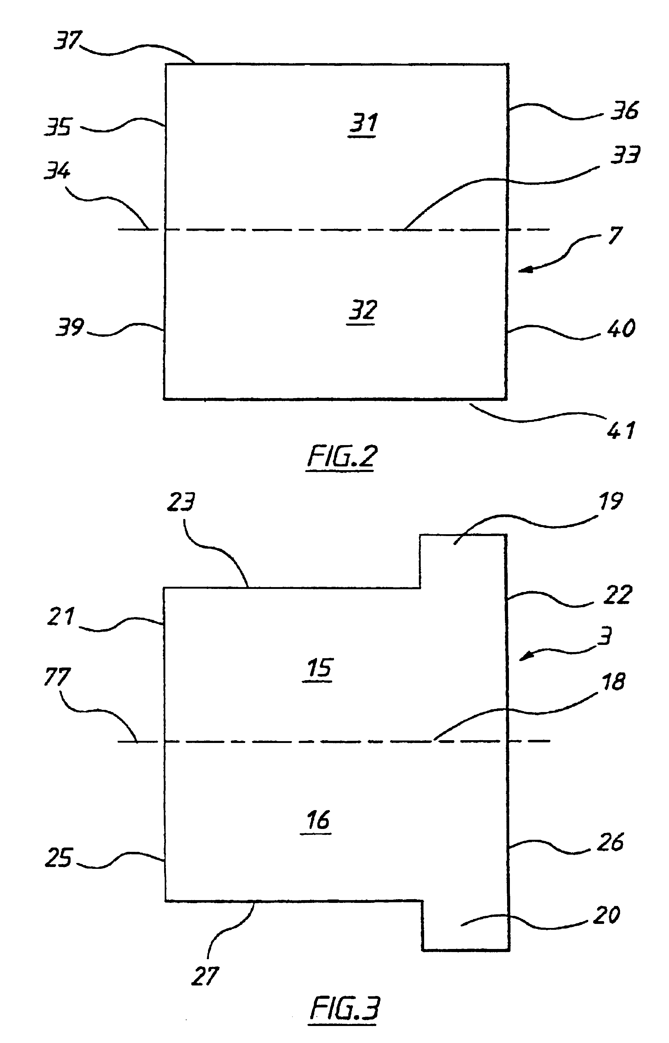
[0076]Referring to FIG. 1, a charge storage device 1 includes a sealed prismatic housing 2. Two opposed folded rectangular aluminium electrodes 3 and 4 are disposed within housing 2 and connected to respective metal terminals 5 and 6 for allowing external electrical connection to the electrodes. A Solupor™ sheet separator 7 is disposed intermediate electrodes 3 and 4 for maintaining those electrodes in a fixed spaced apart configuration. An electrolyte (not shown) is also disposed intermediate the electrodes. Collecting means in the form of a scavenging agent is grafted to separator 7 for sequestering one or more predetermined contaminants from the housing.

[0077]Separator 7 is formed in a “pocket” configuration, wherein it is folded back upon itself and the transverse ends secured together for providing an opening 8 between the transverse ends. For ease of illustration, separator 7 is shown as having two fold lines. In practice, however, a single fold line is used as the separator i...


PUM


Abstract

A charge storage device (1) includes a sealed prismatic housing (2). Two opposed folded rectangular aluminium electrodes (3, 4) are disposed within housing (2) and connected to respective metal terminals (5, 6) for allowing external electrical connection to the electrodes. A porous, electronically insulating separator material, e.g. Solupor™, sheet separator (7) is disposed intermediate electrodes (3, 4) for maintaining those electrodes in a fixed spaced apart configuration. An electrolyte (not shown) is also disposed intermediate the electrodes. Collecting means in the form of a scavenging agent is grafted to separator (7) for sequestering one or more predetermined contaminants from the housing.

Description

FIELD OF THE INVENTION[0001]The present invention relates to a charge storage device.[0002]The invention has been developed primarily for supercapacitors and will be described hereinafter with reference to that application. However, the invention is not limited to that particular field of use and is also suitable for other charge storage devices such as capacitors, batteries, fuel cells and the like.DISCUSSION OF THE PRIOR ART[0003]Supercapacitors in the form of electric double layer capacitors are known. These capacitors generally include a housing for two aluminium electrodes each of which have a coating of activated carbon or the like on at least one side. The electrodes are typically wound or otherwise interleaved together with an intermediate separator and wetted with an appropriate electrolyte. The charge is stored in the electric double layer which is formed between the carbon and the electrolyte. Due to the large surface area per volume of the activated carbon the charge sto...

Claims


Application Information

Patent Timeline
IPC IPC(8): H01G9/02H01G9/00H01M4/02H01M10/36H01M10/40H01G9/058H01G9/155H01M4/36H01M4/38H01M4/62H01M4/96H01M10/52H01M50/466
CPCH01G9/02H01G9/08H01G9/155H01M2/16H01M2/18H01M4/366H01M4/38H01M4/96H01M10/52H01M2/0287H01M2/1223H01M4/621Y02E60/13Y02E60/50Y02E60/10H01M50/124H01M50/317H01G11/20H01G11/82H01G11/26H01G11/38H01G11/52H01M50/466
Inventor PAUL, GEORGE LANGEPYNENBURG, RORY ALBERT JAMESMAHON, PETER JOHNKESHISHIAN, SARKIS
Owner CAP XX LTD
Learn More