
Wound closure system and method

Inactive Publication Date: 2005-09-13
3M INNOVATIVE PROPERTIES CO
View PDF46 Cites 54 Cited by
  • Summary
  • Abstract
  • Description
  • Claims
  • Application Information

AI Technical Summary

Benefits of technology

[0007]The present invention addresses the problems discussed above by providing a system for closing wounds that employs both wound closures and a flowable adhesive skin paint for providing good wound edge opposition in the spaces adjacent to or between the wound closures. The combination of a wound closure that can hold the wound edges closed in the face of substantial forces trying to separate them, and a flowable adhesive that can hold wound edges in excellent opposition but cannot sustain large forces, accomplish much more together than either alone. Unlike previously known systems employing both a wound closure and a flowable adhesive, the skin paint is adhesive to skin but not to the wound closure, and thus mechanical irritation of the skin near the wound is avoided.
[0015]When adhesive skin paints of the type described in U.S. Pat. No. 6,383,502 are in use, the limited adhesion between the wound bridging portion and skin as caused by the adhesive skin paint may be accomplished by fabricating the wound bridging portion from a porous film, e.g., a porous polypropylene film. The porous nature of the film may provide advantages such as allowing the wound to breathe and allowing the solvent portion of any adhesive skin paint that has inadvertently been permitted under the wound bridging portion to evaporate. The porous film may be microporous, where microporous films have pore sizes of about 100 micrometers or less. One example of a suitable microporous film may be a microporous polypropylene film.
[0019]A reinforcing layer that is separate from a backing may be used in the wound bridging portion of the wound closure to provide the desired dimensional stability to the wound bridging portion. That reinforcing layer may take the form of a wound contact layer (i.e., a layer in contact with a wound when in use) if it is located on the patient side of the wound closure. Alternatively, for example, the reinforcing layer may be located on the side of the backing facing away from the wound. In still another alternative, a reinforcing layer may be provided on both sides of the backing in the wound bridging portion.
[0022]In some embodiments, the wound bridging portion may have a width less than a width of the end portions. This permits maximum visualization of the wound area without sacrificing the surface area where the skin adhesive contacts the patient's skin. It may also be convenient to have the opposing end portions have unequal lengths as measured from the wound bridging portion to the ends of the wound closure. This sometimes facilitates placing the wound closure when features such as the eye are near the wound site.

Problems solved by technology

The combination of a wound closure that can hold the wound edges closed in the face of substantial forces trying to separate them, and a flowable adhesive that can hold wound edges in excellent opposition but cannot sustain large forces, accomplish much more together than either alone.

Method used


Image

  • Wound closure system and method
  • Wound closure system and method
  • Wound closure system and method

Examples


Embodiment Construction

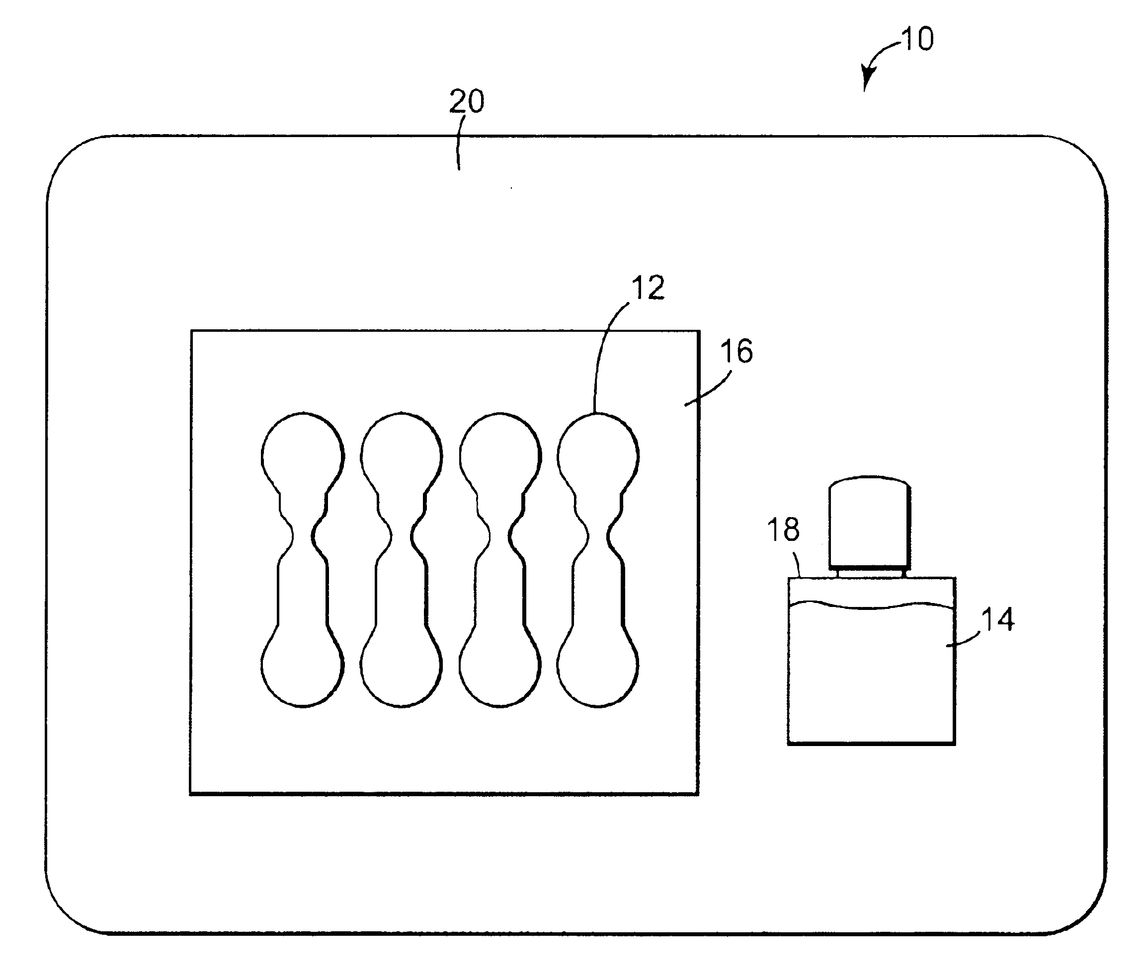
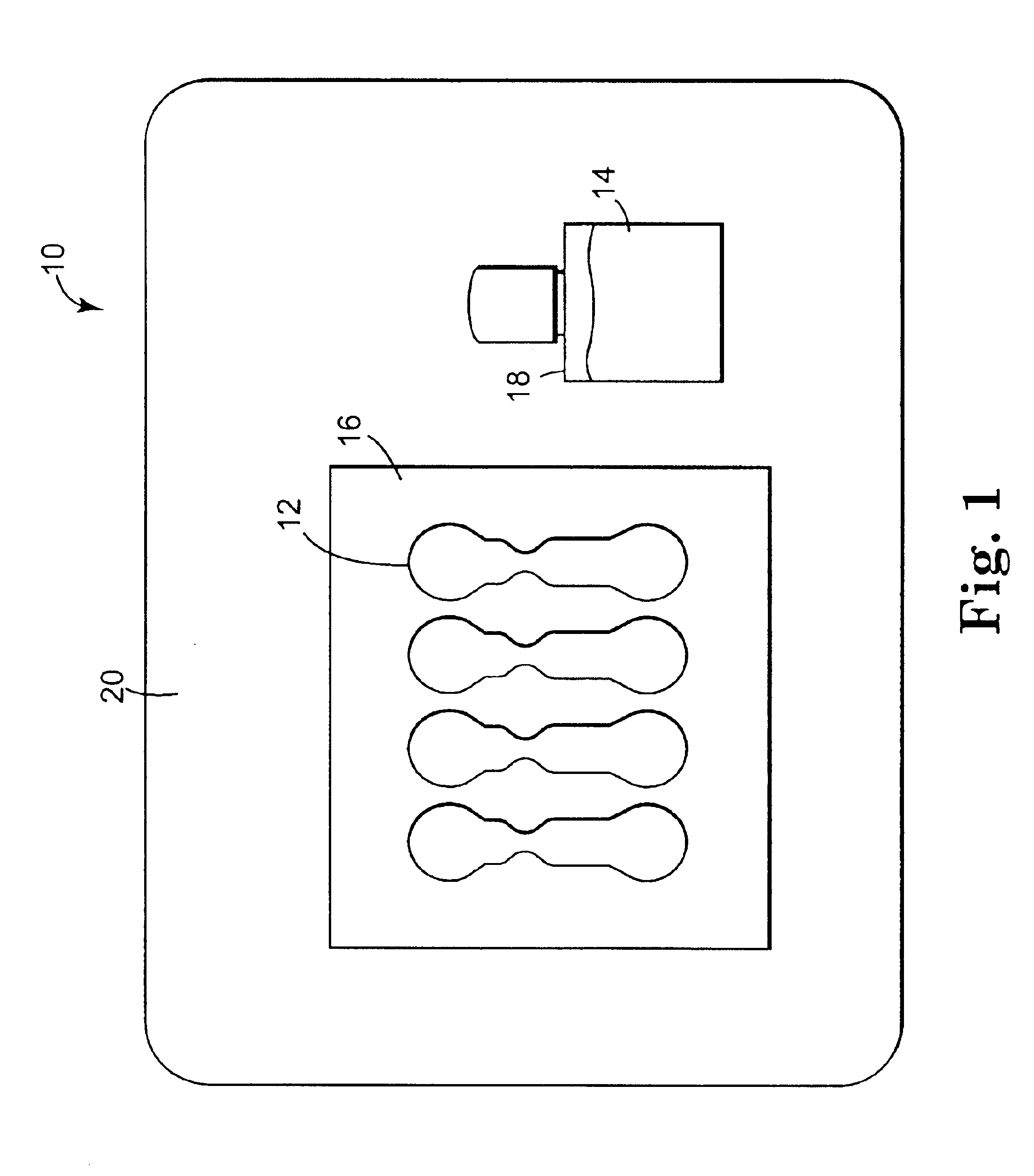
[0032]Referring now to FIG. 1, an exemplary wound closure system 10 is illustrated in the form of a kit. The kit 10 includes wound closures 12 and a quantity of adhesive skin paint 14. The wound closures 12 may be mounted on a release liner 16, while the adhesive skin paint 14 may be provided in a dispensing bottle 18 or other container. The system 10 may preferably be provided in a package 20. In some embodiments, the package 20 may be adapted to cooperate with some method for sterilizing the kit, e.g. the package may include a layer of a spun bonded polyolefin (such as TYVEK) which is permeable to ethylene oxide gas.

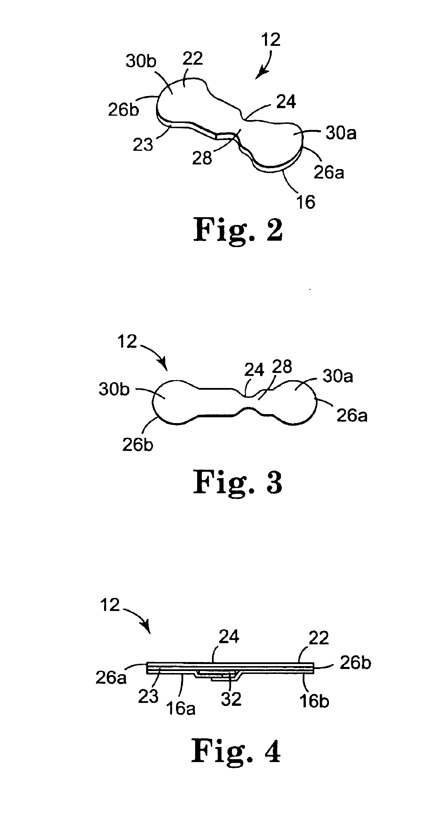
[0033]Referring now to FIGS. 2 and 3, an exemplary wound closure 12 is illustrated in isolation. The wound closure 12 has a backing 22 and a layer of skin adhesive 23 contacting the backing. In the embodiment depicted in these figures, the release liner 16 is shown diecut to size rather than cut to support several wound closures as in FIG. 1. In either case the release...


PUM


Abstract

Methods and systems for closing wounds using wound closures and a flowable adhesive skin paint are disclosed. The flowable adhesive does not adhere the wound closures to the skin over the wound to reduce irritation. In some embodiments, the skin paint may include 1-40% of a siloxane-containing polymer; 60-99% of an Alkane-Based Siloxane Polymer Reaction Solvent; and 0-15% of adjuvants. The wound closures used with such a skin paint may include a wound bridging portion of microporous polypropylene film.

Description

TECHNICAL FIELD[0001]The invention relates generally to the treating and closing of wounds using adhesive wound closures and adhesive skin paints.BACKGROUND[0002]In medicine, sutures have long been used to close wounds. More recently, adhesive closures have been introduced that can effectively close some types of wounds without inflicting the additional injury inherent in suturing. These adhesive closures have a backing to provide solid structure, and have an adhesive layer for adhering to the skin. There are two main criteria that must be reconciled in a successful design for these products: reliable adhesion to the skin, even when the wound is adjacent to a joint; and good performance in keeping the wound edges in proximity to each other.[0003]One approach is to use a non-woven web as the basic backing, and to reinforce this material with strong fibers in the longitudinal, or cross-wound, direction. The main substance of the backing can bend with the skin as the patient moves, and...

Claims


Application Information

Patent Timeline
IPC IPC(8): A61F13/02A61B19/00A61B19/02A61L15/16A61L15/58A61L26/00A61B17/03A61B17/08A61B17/00A61L24/00
CPCA61B17/085A61L26/0061A61F13/02A61L15/58A61B19/026A61B17/00491A61B50/30A61F13/0243A61F13/0253
Inventor DUNSHEE, WAYNE K.
Owner 3M INNOVATIVE PROPERTIES CO
Learn More