[0017]As discussed herein, the present invention finds suitable application in a number of different environments. The invention is particularly useful for the provision of reinforcement in automotive vehicles, particularly to help provide
energy distribution control in response to a force. The preferred shape and structure of the reinforcing member will depend upon where it is to be located in the vehicle structure and the function it is to perform. For example, if it is to be located in the front longitudinal section of the vehicle it might be designed for
impact resistance. On the other hand, it may be designed to reduce point mobility such as for example at the base of side and rear pillars in the vehicle. The reduction of point mobility is particularly important with high-sided vehicles where the reinforcement can help reduce or prevent vehicle sway thus potentially reducing
metal fatigue. Other applications include the resistance of deformation of the rear longitudinal section, in particular to prevent upward deformation from
rear impact. Other parts of a vehicle which may be reinforced by the techniques of the present invention include roof structures, pillars, frame cross members such as the engine cradle and window frames particularly rear window frames.
[0018]The expandable
adhesive material serves two main functions, it will expand to fill the space between the reinforcing member and the interior of the hollow member and it will also bond to the interior wall of the hollow member. Accordingly, expandable adhesive material means that the material can be activated to both expand (typically foam) and to act as an adhesive, at the conditions, e.g., temperature, at which it expands. Activation therefore enables the expandable material to expand and fill a gap between the reinforcing member and the hollow structural member it is designed to reinforce and to bond to the internal surface of the hollow structure. Accordingly the expandable adhesive expands at the desired temperature and is sufficiently adhesive to firmly bond the reinforcing member to the interior surface of the hollow structural member.
[0019]While it is not essential, it is preferred that prior to activation the expandable adhesive material is dry and not tacky to the touch. This facilitates shipping and handling of the structural reinforcing member and helps prevent
contamination. Examples of preferred expandable
adhesive materials include foamable
epoxy-base resins and examples of such materials are the products L5206, L5207, L5208 and L5209, which are commercially available from L & L Products of Romeo Michigan USA, and the Betacore Products BC 5204, 5206, 5207, 5208 and 5214 available from Core Products, Strasbourg, France. The expandable adhesive material should be chosen according to the rate of expansion and foam densities required. It is further preferred that it expand at the temperatures experienced in a
coating bake oven, such as an electrocoat process oven, typically 130° C.-200° C. Alternatively the material may be expanded by
infrared high frequency,
moisture,
microwave or
induction heating which are particularly useful in systems which do not employ the electrocoat process.
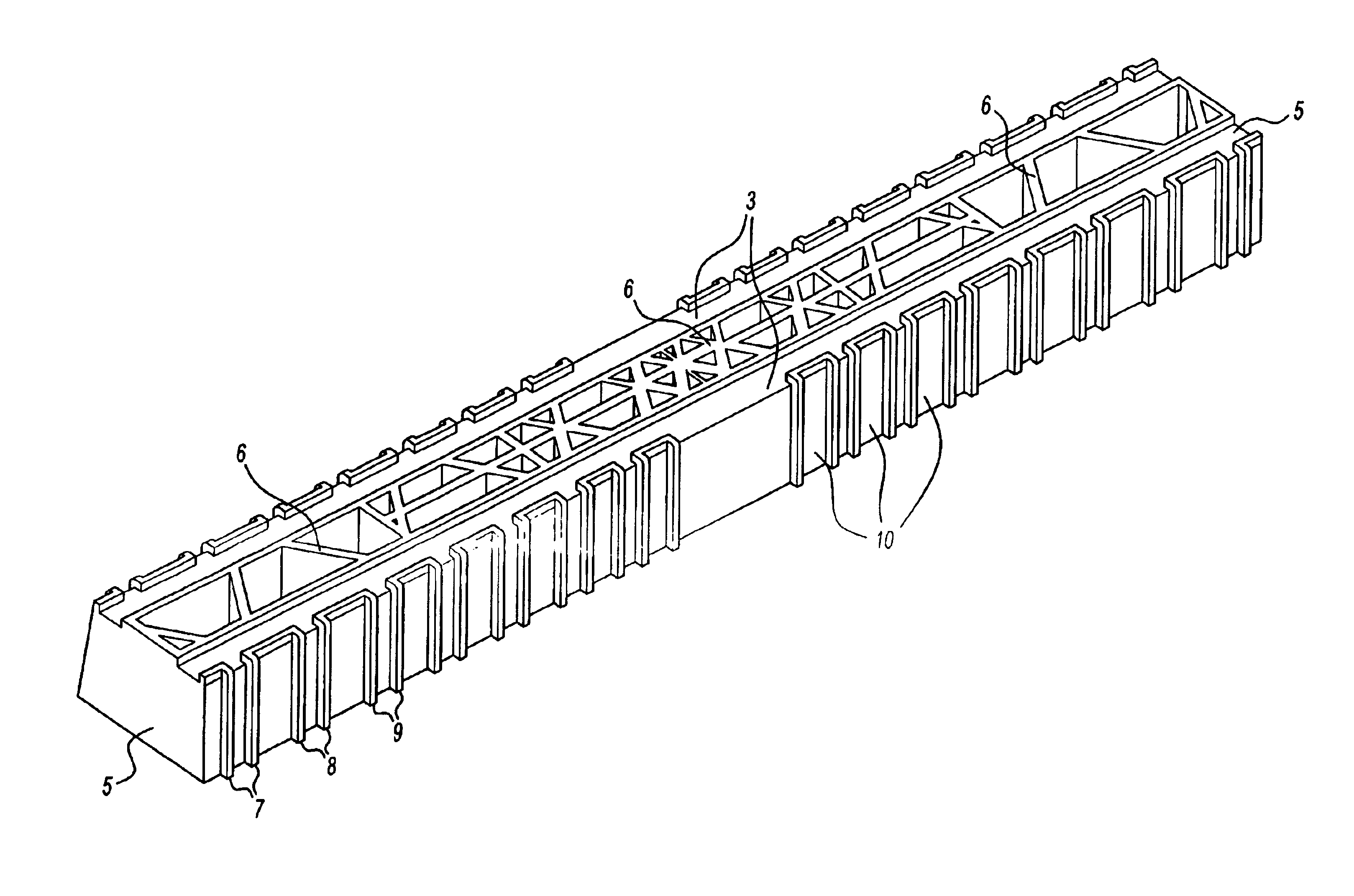
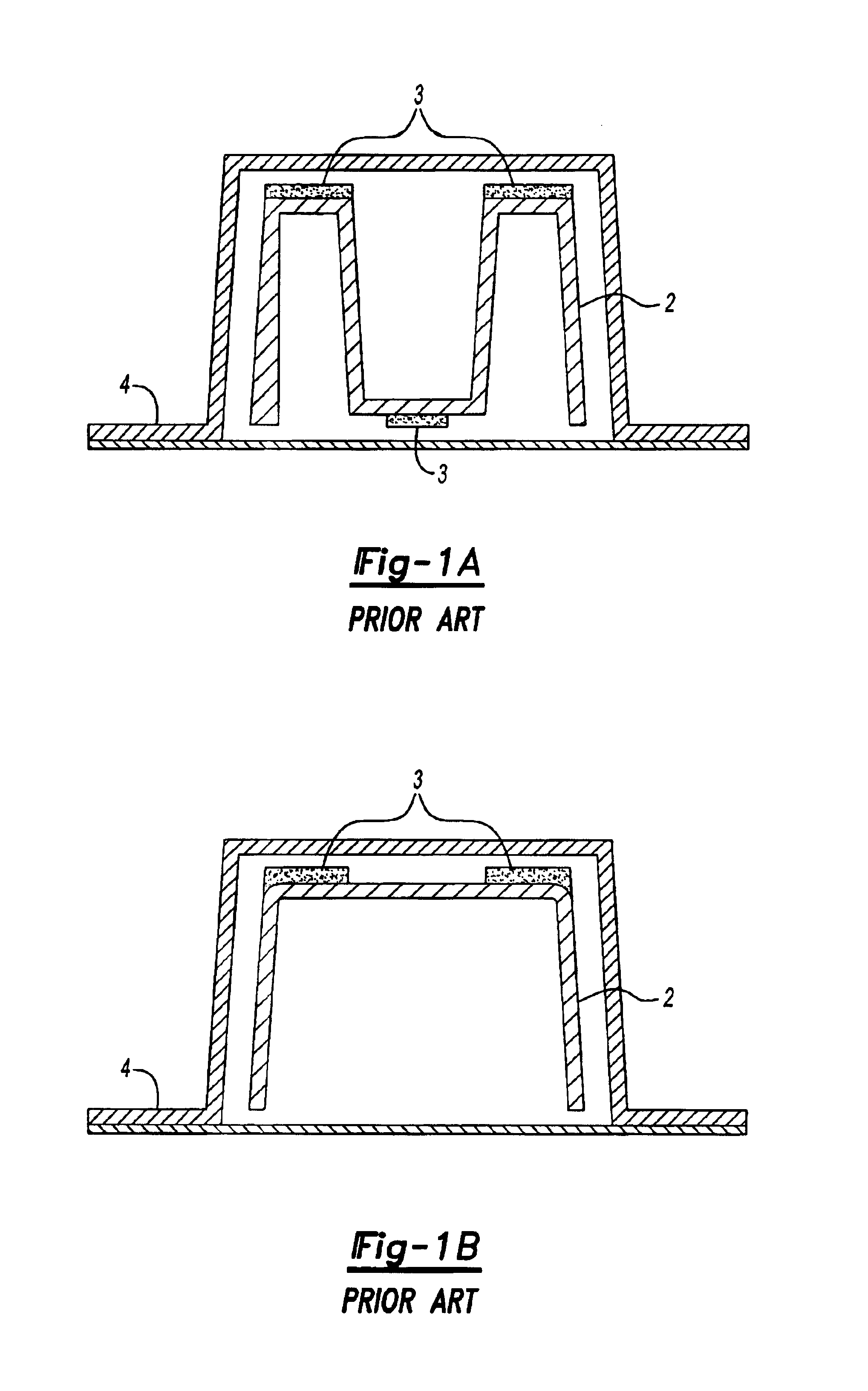
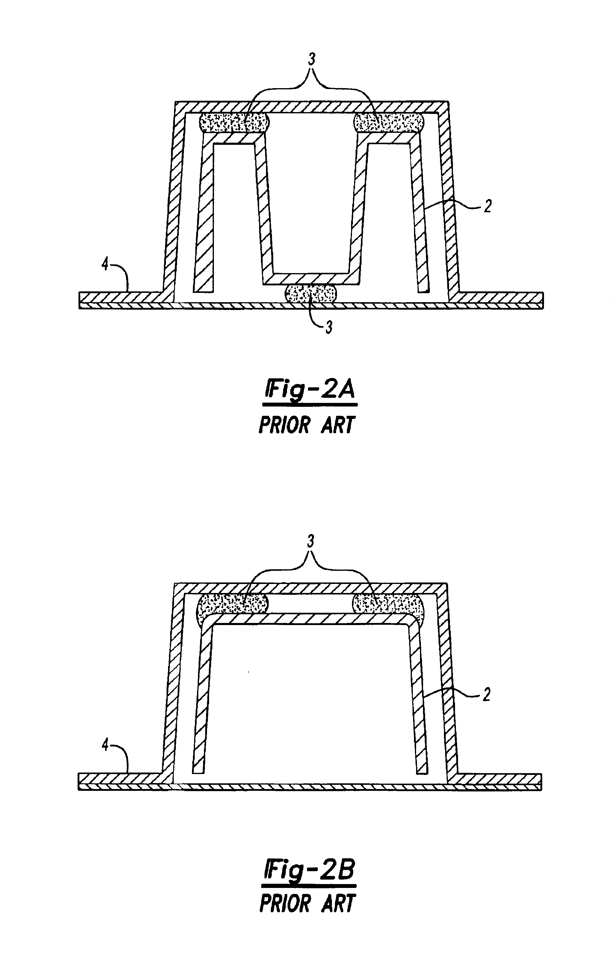
[0020]The expandable material is applied to the surface of the reinforcing member at a location where its direction of expansion is controlled by at least one of the extensions formed on the surface of the reinforcing member. In a preferred embodiment the reinforcing member is provided with two or more ribs and the expandable material is provided between the ribs. In this way the reinforcing member may be located within the hollow structural member so that the extremities of the ribs are close to the inner surface of the hollow structural member, thereby helping to increase the resistance to deformation of the hollow structural member. At the same time at least one of the ribs directs the expansion of the expandable adhesive material through the channel formed between the ribs towards the inner surface of the hollow structural member. In this way an effective bond between the rigid reinforcing member and the hollow structural member may be achieved with a reduced amount of expandable adhesive material.
[0024]It is preferred that the reinforcing member coated with the expandable adhesive material is located within the hollow structural member that it is designed to reinforce in a manner that provides a clearance between the external surface of the coated member and the internal surface of the hollow structural member. This allows for the passage of a
coating fluid, such as electrocoat fluid, between the hollow structural member and the internal surface and also enables a uniform expansion of the foam around the member to provide more uniform reinforcement.
[0025]Accordingly in a preferred process for providing reinforcement within a hollow structural member such as a
vehicle frame, moulded reinforcing members provided with extensions and with a layer of expandable material thereon adjacent to extensions are installed during
assembly of the
vehicle frame. Locating lugs are preferably moulded into the reinforcing member or the expandable material so that the reinforcing member sits within the hollow structural member leaving a space between the member and the interior walls of the hollow structural member to be reinforced. In this way, it is possible to avoid any need for fastening or bonding means to attach the member to the interior walls of the hollow structural member. The assembled structure may then be coated. For instance, the assembled structure may then be subjected to the electrocoat process in which it is passed through a bath of
coating material and a
corrosion resistant coating is deposited onto the structure by
electrolysis. The vehicle structure is then dried in an oven to cure the coating. The expandable material is preferably chosen so that it is activated to expand and develop adhesive properties by the conditions used in the oven employed to cure the coating. The expandable material will therefore expand under the curing conditions to provide both a foam that fills the space between the member and the interior walls of the hollow structural member and a strong bond between the reinforcing member and the interior wall of the hollow structural member. Typically the coated structure is cured at around 80 to 200° C. (e.g., 165° C.) for about 5 to 40 minutes (e.g., above 20 minutes) and accordingly the expandable adhesive material should be activated under these conditions. The automobile industry is however looking to use lower curing temperatures and shorter
drying times and this may influence the choice of expandable materials.


