
System for automated screening of security cameras

a security camera and automatic screening technology, applied in the field of security systems, can solve the problems of increasing the risk of auto theft and auto burglary in parking garages so equipped, and owners may face difficult to defend claims, so as to reduce the number of floating point calculations

Inactive Publication Date: 2005-09-06
CHECKVIDEO
View PDF22 Cites 267 Cited by
  • Summary
  • Abstract
  • Description
  • Claims
  • Application Information

AI Technical Summary

Benefits of technology

"The present invention provides a novel and advantageous security system using a novel and improved method for automated screening of security cameras. The system is cost-effective, can be used in conjunction with large conventional CCTV systems, and reduces operator fatigue. It achieves this by using intelligent electronic methods to select and control which cameras should be viewed by operators based on video content and the presence of relevant objects or people. The system also includes advanced image analysis techniques to automatically identify and track vehicles and pedestrians, and to distinguish between them. Overall, the system provides a more efficient and effective way to monitor security in CCTV systems."

Problems solved by technology

If then there is an event of loss or injury that might have been prevented had the system been functioning properly and to its full capacity, the owner may be confronted with a claim difficult to defend.
Although parking garages provide a valuable benefit and highly desirable or necessary service to the public by offering parking facilities for vehicles of members of the public, they may nevertheless present risk to members of the visiting public.
But even parking garages so equipped may be increasingly subject to risk of auto thefts and auto burglaries when these garages are located adjacent to quick escape routes such as freeway on-ramps or major thoroughfares.
Yet, even in a small system, it is difficult or impossible for one such person to watch the same scene or scenes continuously.
After a few minutes of the same view, what may be termed attention fatigue sets in.
In a large CCTV system having hundreds of cameras, the fatigue factor is extreme for security personnel who must observe a correspondingly large number of display monitors.
In such a system, presenting one view per minute on a display monitors will not allow operators to detect quickly occurring events such as purse snatching.
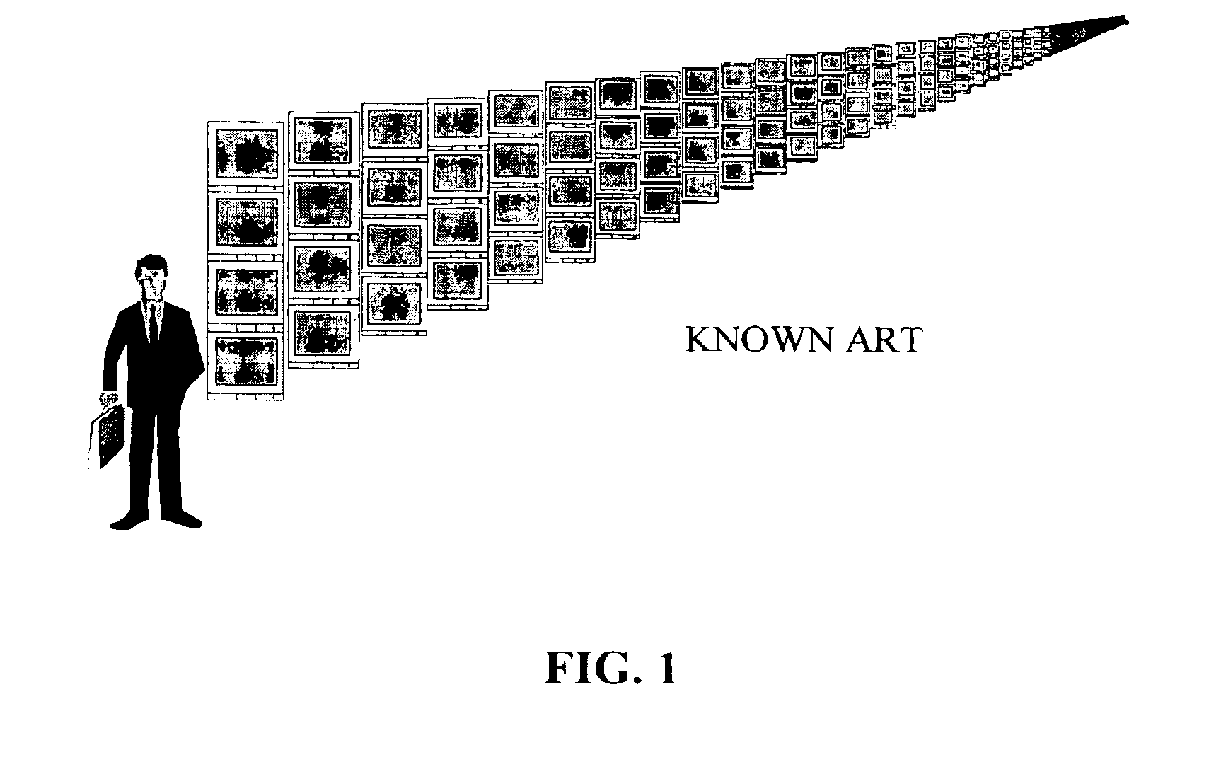
Even if resultant high costs of such staffing are sustainable, security personnel cannot practically be expected to maintain a satisfactorily high level of attention for adequate incidence discernment, because such personnel are presented on the display monitors with some 11,520 individual scenes to evaluate during each 8-hour shift.
However, if such a wall of monitors 137 feet in length were to be employed, it is improbable that any crime event or other incident would be seen.
Although the human figure is not drawn to scale, the operating viewing situation or requirements for such a wall of monitors can easily be visualized, and will readily be realized as being impractical for a large quantity of monitors.
Even if the security budget will allow for payment of 30 salaries for operating personnel, the monitoring task would drive these operators to extreme attention fatigue within any given shift.
As the number of cameras in the proposed system was postulated to grow, the weakness of simple motion detection could become apparent.
Commercially available motion detectors for such a system are found to be unable to distinguish a person from a vehicle.
About six operators would be required to be on duty during the day, and the repetitive presentation of views caused by movement of a single vehicle past multiple cameras would cause extreme boredom and resulting lack of attention.
However, the known art does not fully address the need for intelligent camera selection based on a plurality of inputs for decreasing operator load and fatigue.
Additionally, the known art does not control CCTV switching for operator viewing.

Method used


Image

  • System for automated screening of security cameras
  • System for automated screening of security cameras
  • System for automated screening of security cameras

Examples


Embodiment Construction

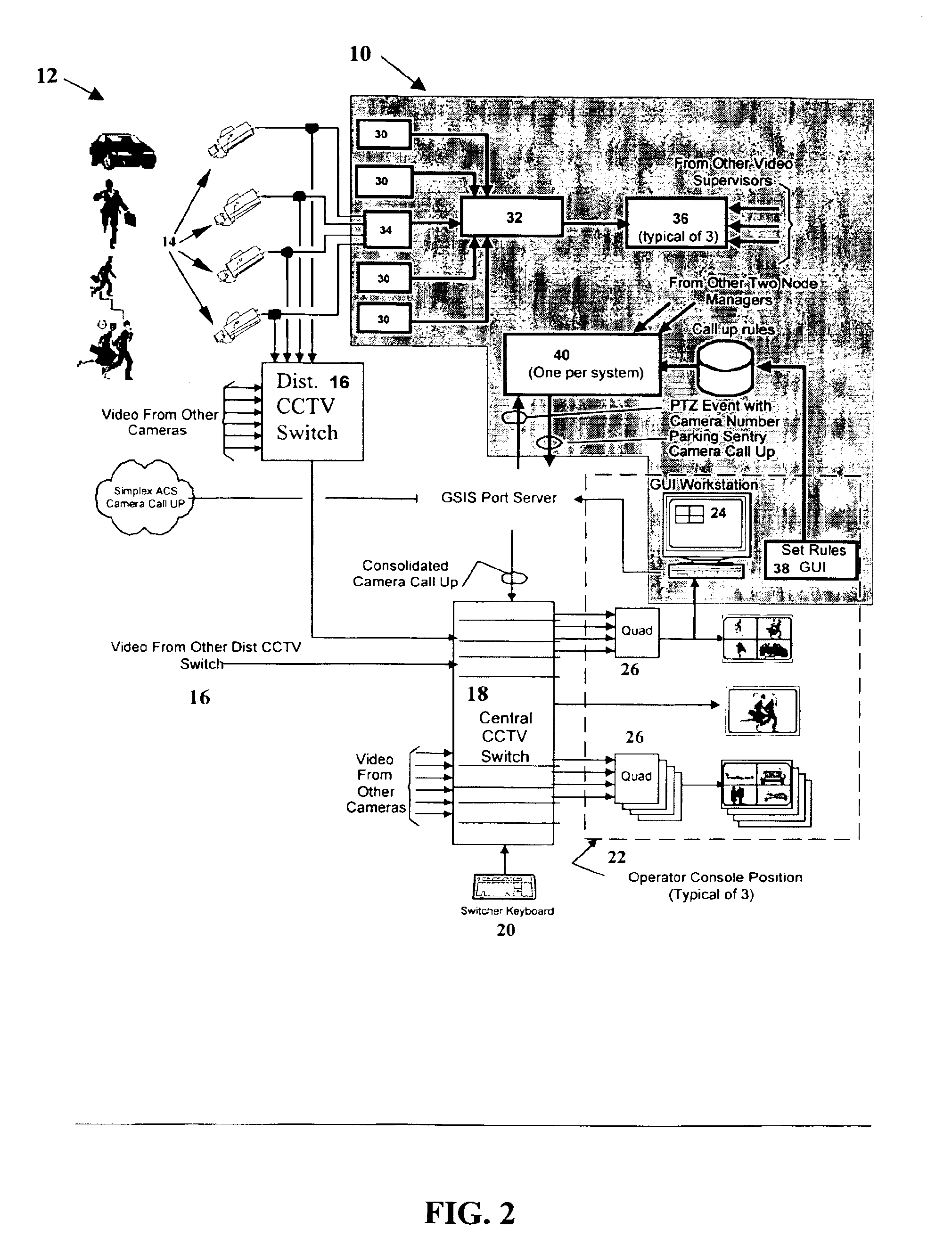
[0089]Referring to the drawings, and in particular to FIG. 2, software components of processor-controlled selection and control system (PCS) 10 are shown in boxes in the upper right area, as contained within the broken dash-and-dot border. Other components in the figure reflect the block diagram of CCTV subsystem12 used in connection with electronics features including the software-driven components in accordance with the inventive system configuration. The software-driven components of the electronics subsystem cause video outputs from video cameras of the CCTV subsystem to be automatically and selectively made available to display monitors of the CCTV system, where the camera views may be viewed by security personnel who observe the display monitors, by video selectively supplied to one video display console for an operator, or to more such consoles.

Existing CCTV System

[0090]It will be assumed for purposes of explaining the new system that it includes, as in the example given abov...


PUM


Abstract

The present invention involves a system for automatically screening closed circuit television (CCTV) cameras for large and small scale security systems, as used for example in parking garages. The system includes six primary software elements, each of which performs a unique function within the operation of the security system to provide intelligent camera selection for operators, resulting in a marked decrease of operator fatigue in a CCTV system. Real-time image analysis of video data is performed wherein a single pass of a video frame produces a terrain map which contains parameters indicating the content of the video. Based on the parameters of the terrain map, the system is able to make decisions about which camera an operator should view based on the presence and activity of vehicles and pedestrians, furthermore, discriminating vehicle traffic from pedestrian traffic. The system is compatible with existing CCTV (closed circuit television) systems and is comprised of modular elements to facilitate integration and upgrades.

Description

CROSS-REFERENCE TO RELATED APPLICATIONS[0001]This application is based upon Provisional Patent Application, Ser. No. 60 / 180,323, entitled “System for Automated Screening of Security Cameras”, filed 4 Feb. 2000, the contents of which are incorporated herein by reference in their entirety and continued preservation of which is requested.BACKGROUND OF THE INVENTION[0002]1. Field of the Invention[0003]The present invention relates to security systems and, more particularly, to an advantageous new system involving methods and apparatus for automated screening of security cameras, as in large-scale security CCTV (Closed Circuit Television) systems.[0004]2. Prior Art[0005]Security systems, as used for example in parking garages, provide one of the few areas where an owner may feel that it is necessary to employ installed security technology to its full capacity. When a security system is installed there may be implicit acknowledgment of the need for reliable dependence on the system and it...

Claims


Application Information

Patent Timeline
Patent Type & Authority Patents(United States)
IPC IPC(8): G06K9/32H04N7/18G06T1/00G06T7/00G06T7/20
CPCG06K9/00771H04N7/181H04N7/18G06V20/52
Inventor GAROUTTE, MAURICE V.
Owner CHECKVIDEO
Learn More