
Optical communication system using 4 wavelength add/drop type wavelength division multiplexing

a communication system and add/drop technology, applied in multiplex communication, optical elements, instruments, etc., can solve the problems of not being profitable for mobile communication service companies, not being able to use microwave or laser repeater systems, and the multiplexing apparatus is not that simple, so as to extend the communication coverage, the effect of high quality and extending the communication coverag

Inactive Publication Date: 2005-08-30
A & P TELECOM
View PDF12 Cites 2 Cited by
  • Summary
  • Abstract
  • Description
  • Claims
  • Application Information

AI Technical Summary

Benefits of technology

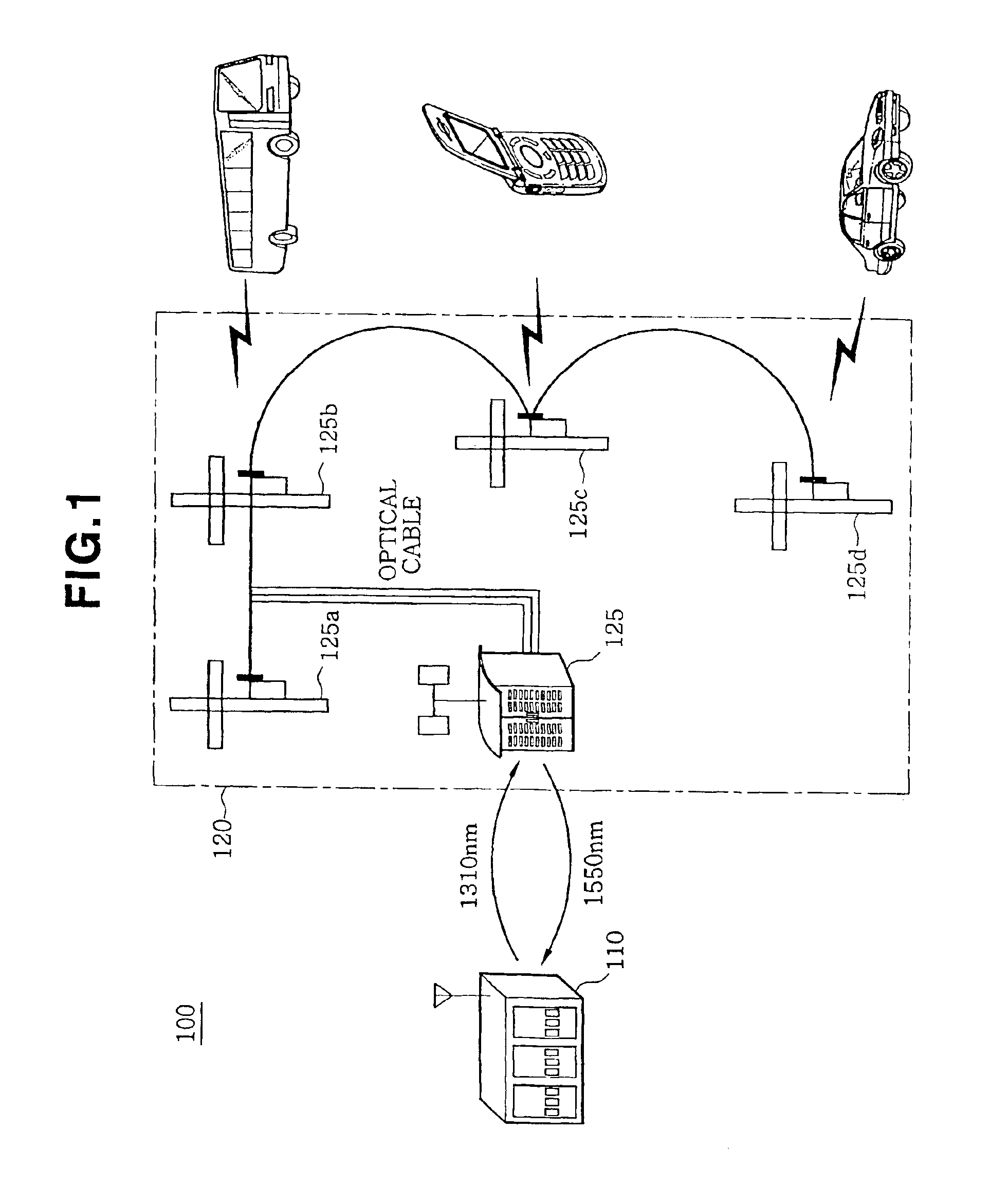
[0009]Accordingly, to solve the above problems, it is an object of the present invention to provide an optical communication system using a four-wavelength add / drop type wavelength division multiplexer, through which a low-cost optical communication service can be provided without increasing optical cables by installing a slave unit composed of a wavelength-pass add / drop type four-wavelength optical module in an optical communication system using existing 1:1 mode wavelength division multiplexing using wavelengths of 1310 nm and 1550 nm.
[0011]According to the present invention, slave units are connected between a base station and a master unit so that the slave units can communicate with each other. The slave units are installed at an existing optical line without additionally installing an optical line, thereby extending a communication coverage at low cost and realizing reliable communication. In other words, the present invention allows an existing base station to communicate with an existing master unit as in conventional systems and allows slave units to independently communicate with each other. In addition, a fiber type or micro-lens type filter is used for each line to adjust an isolation ratio to about 60 dB, thereby accomplishing wavelength blocking to prevent interference between adjacent wavelengths. The isolation ratio can be freely changed within a range from 25 dB to 60 dB when necessary.

Problems solved by technology

However, to fulfill the requirement, it is necessary to build base stations in areas where telephone traffic is low at enormous expense, which is not profitable for mobile communication service companies due to inefficiency of investment and causes waste of national resources.
When the geographical features of Korea having more than 80% of the land occupied by mountains and hills are considered, there is much limitation in using a microwave or a laser repeater system needing to secure the line-of-sight between a base station and a repeater station.
Such a multiplexing apparatus is not that simple it is in an existing communication cable network.
However, conventional optical communication systems have the following problems.
In this case, additional installation of optical cables needs additional expenses, increasing financial burden on communication service companies.
Second, since slave units are not controlled by a base station but are controlled by a master unit, communication between slave units is restricted.
Third, in a multiplexing method using optical couplers, it is difficult to change wavelengths, and big and small loss according to a divergence ratio occurs during transmission.
Since a fixed particular wavelength is used to distribute a desired wavelength or mix desired wavelengths using an optical coupler, it is difficult to adapt a conventional optical communication system to a flexible environment.

Method used


Image

  • Optical communication system using 4 wavelength add/drop type wavelength division multiplexing
  • Optical communication system using 4 wavelength add/drop type wavelength division multiplexing
  • Optical communication system using 4 wavelength add/drop type wavelength division multiplexing

Examples


Embodiment Construction

[0016]Hereinafter, a preferred embodiment of an optical communication system using a four-wavelength add / drop type wavelength division multiplexer according to the present invention will be described with reference to the attached drawings.

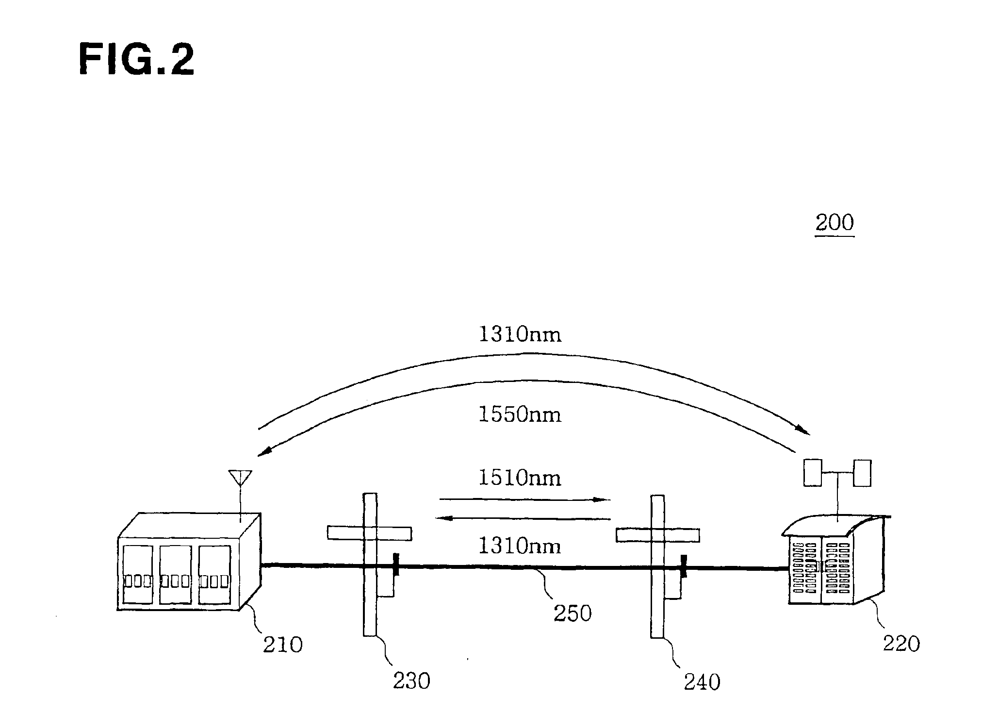
[0017]FIG. 2 is a schematic diagram of an optical communication system 200 according to the present invention. The optical communication system 200 includes a base station 210, a master unit 220, and slave units 230 and 240. The members of the optical communication system 200 are connected through an optical cable 250. Although only two slave units 230 and 240 are shown in FIG. 2, it will be apparently understood by those skilled in the art that more slave units can be connected according to an environment to which the present invention is applied.

[0018]The base station 210 serves as a bridge connecting an exchange (not shown) to mobile terminals. The base station 210 is connected to the exchange through a wire network and connected to mobile term...


PUM


Abstract

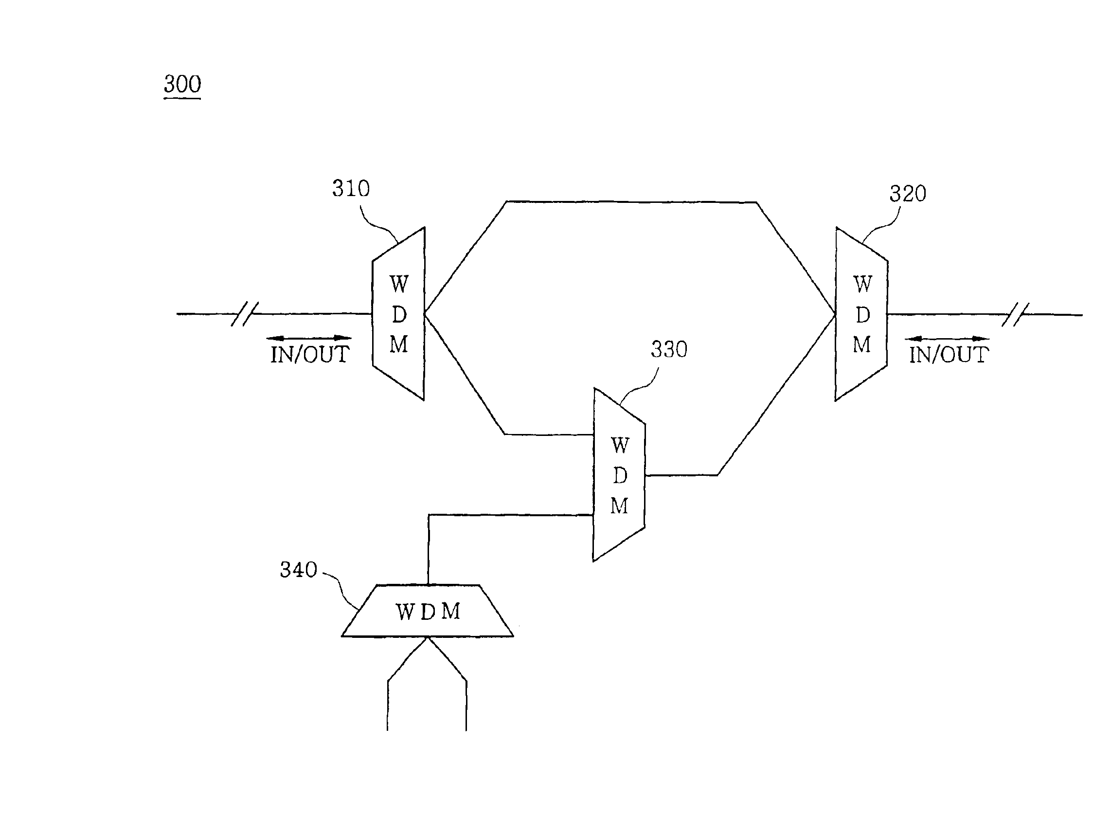
An optical communication system using a four-wavelength add / drop type wavelength division multiplexer (WDM) is provided for extending a communication coverage without adding an optical line and a repeater by installing a wavelength-pass add / drop type optical module at an optical line connected between an existing transmitting station or base station and an existing receiving station or repeater. The optical communication system includes a slave unit including, a first WDM for dividing or mixing a first wavelength and a second wavelength, a second WDM which is connected to the first WDM and divides or mixes the first wavelength and the second wavelength to allow them travel through a predetermined path, a third WDM which is connected to the first WDM and divides a third wavelength and a fourth wavelength from a communication line of the second wavelength; and a fourth WDM which is connected to the second WDM and multiplexes or demultiplexes the third wavelength and the fourth wavelength. Accordingly, by installing slave units at an optical line connected to an existing base station and an existing master unit, the base station can communicate with the master unit without distortion or loss of a signal and the slave units can communicate with each other.

Description

TECHNICAL FIELD[0001]The present invention relates to an optical communication system using a four-wavelength add / drop type wavelength division multiplexer, and more particularly, to an optical communication system for extending a communication coverage without adding an optical line and a repeater by installing a wavelength-pass add / drop type optical module at an optical line connected between an existing transmitting station or base station and an existing receiving station or repeater.BACKGROUND ART[0002]Recently, with development of mobile communication service, high-quality service for non-service areas from secluded places among the mountains and remote islands which are not covered by mobile communication service to basements and apartment areas which are left as poor propagation areas in downtowns is required. However, to fulfill the requirement, it is necessary to build base stations in areas where telephone traffic is low at enormous expense, which is not profitable for mo...

Claims


Application Information

Patent Timeline
Patent Type & Authority Patents(United States)
IPC IPC(8): H04J14/02H04B10/26
CPCH04J14/0209H04J14/0213H04J14/0216H04J14/0226H04J14/0247H04J14/0252H04J14/02H04J14/0282H04J14/0307H04B10/2581H04B10/25
Inventor KIM, TAE-KWON
Owner A & P TELECOM
Learn More