Reducing actuator arm oscillation during settle mode in a disc drive servo system

a disc drive servo system and actuator arm technology, applied in the field of data handling devices, can solve the problems of oscillation of the head, adversely affecting data transfer rate performance, and limitations of these and other prior art approaches

Inactive Publication Date: 2005-08-30
SEAGATE TECH LLC
View PDF28 Cites 14 Cited by
  • Summary
  • Abstract
  • Description
  • Claims
  • Application Information

AI Technical Summary

Benefits of technology

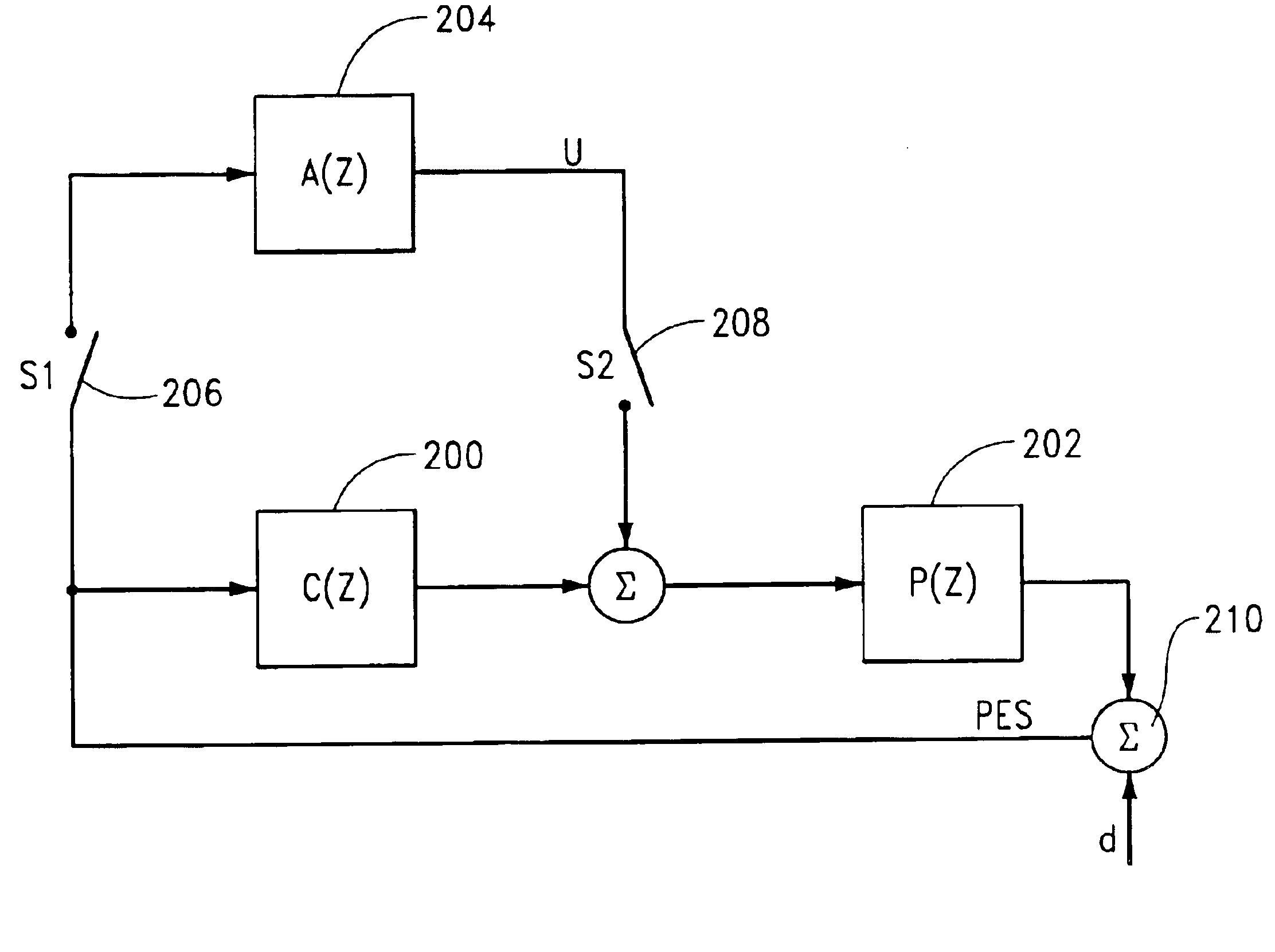
[0014]The application of the compensation signal produces a notch in an error sensitivity function relating the position error signal to an actuator arm oscillatory disturbance. The notch is nominally centered at the frequency of oscillation of the actuator arm. The filter is preferably implemented in firmware used by a programmable servo processor configured to carry out head control operations.

Problems solved by technology

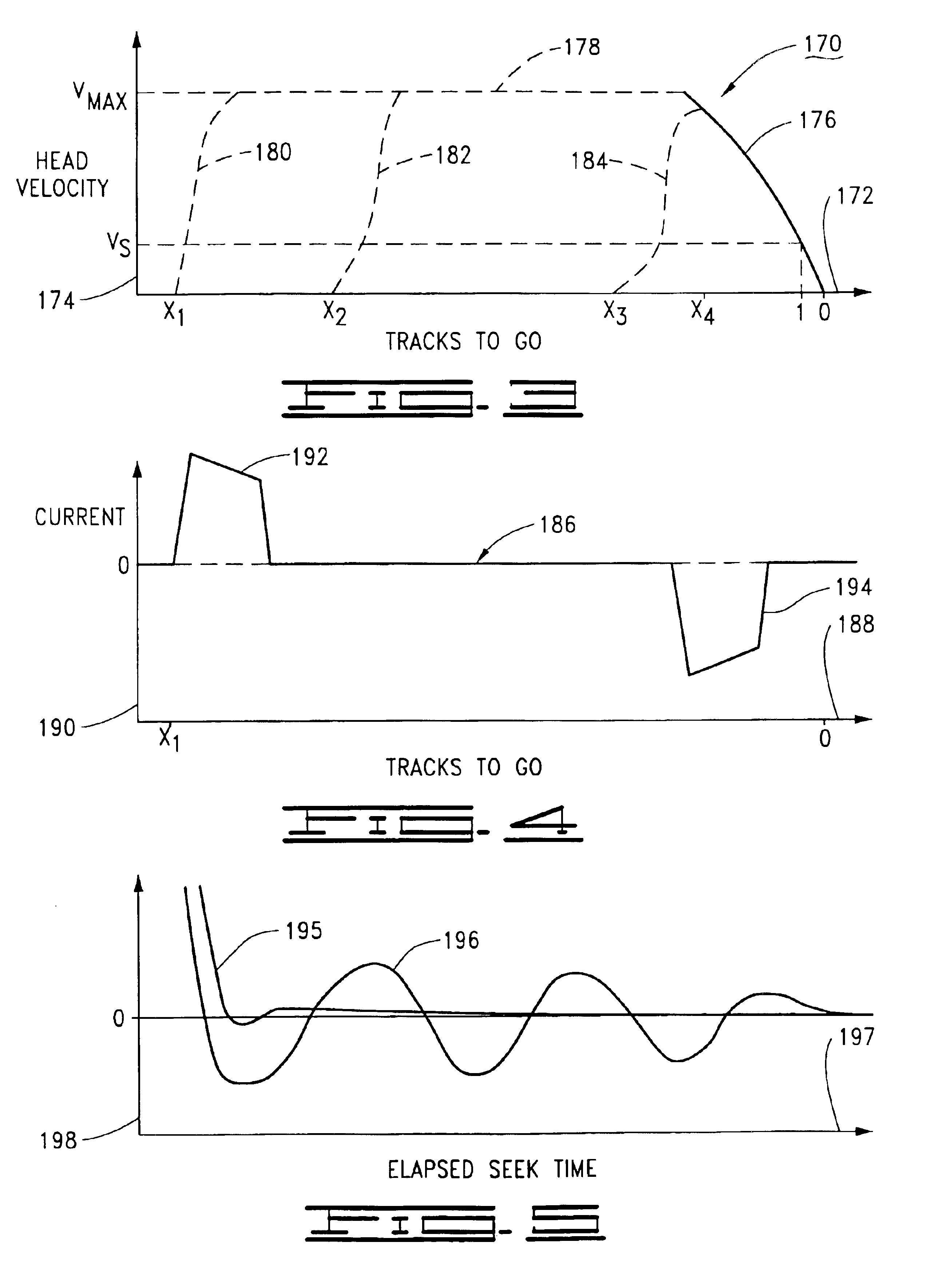
A problem that can arise during a seek is oscillation of the head caused by resonance mode excitation of the actuator arm.
Such oscillation can undesirably extend the total seek time, adversely affecting data transfer rate performance.
While operable, there are limitations associated with these and other prior art approaches.
Changing the current profile to reduce excitation can degrade servo performance by increasing acceleration and deceleration times. Modifying the physical actuator assembly structure to change the mechanical response can be costly and does not lend itself to individual tuning for different electrical offset / mechanical tolerance combinations present within a population of drives during manufacturing.
The use of adaptive tables resident in memory imposes a latency cost to access and retrieve a value at each servo interrupt, and this cost becomes increasingly burdensome at higher servo sample rates and with the compensation of larger numbers of harmonics.

Method used


Image

  • Reducing actuator arm oscillation during settle mode in a disc drive servo system
  • Reducing actuator arm oscillation during settle mode in a disc drive servo system
  • Reducing actuator arm oscillation during settle mode in a disc drive servo system

Examples


Embodiment Construction

[0026]Referring to the drawings in general, and more particularly to FIG. 1, shown therein is a top view of a disc drive data handling system 100 (hereinafter “disc drive”) constructed in accordance with preferred embodiments of the present invention. The disc drive 100 includes a head / disc assembly (HDA) 101 which houses various mechanical components of the disc drive 100, and a disc drive printed circuit board assembly (PCBA) which supports various electronic communication and control circuits. The PCBA is affixed to the underside of the HDA 101 and is therefore not visible in FIG. 1.

[0027]The HDA 101 includes a base deck 102 which, in cooperation with a top cover 104 (shown in partial cut-away), forms an internal housing for the disc drive 100. A spindle motor 106 rotates a number of recording discs 108 in an angular direction indicated at 109. An actuator 110 rotates about a cartridge bearing assembly 112 and includes a number of rigid actuator arms 114 which support flexible su...


PUM

PropertyMeasurementUnit
resonant frequencyaaaaaaaaaa
oscillation frequencyaaaaaaaaaa
frequencyaaaaaaaaaa

Abstract

An apparatus and method for compensating actuator arm oscillation induced by resonance mode excitation during a seek in a disc drive data handling system. The actuator arm supports a head adjacent a recording surface, and a servo loop controls the position of the actuator arm. A frequency of actuator arm oscillation is identified, after which a seek is initiated to move the head from an initial track to a destination track on the recording surface. A position error signal (PES) is generated to indicate position of the head relative to the destination track, and a compensation signal is generated by a filter based on the PES and the frequency of oscillation of the actuator arm. The compensation signal is adapted to remove a component of the PES arising from the actuator arm oscillation, and is applied to the servo loop as the head is settled onto the destination track.

Description

RELATED APPLICATIONS[0001]This application claims priority to Provisional Application No. 60 / 210,645 filed Jun. 9, 2000.FIELD THE INVENTION[0002]This invention relates generally to the field of data handling devices, and more particularly, but not by way of limitation, to a method and apparatus for improving servo performance in a disc drive by reducing actuator arm oscillation at the conclusion of a seek.BACKGROUND[0003]Disc drives are used as primary data storage devices in modern computer systems and networks. A typical disc drive comprises one or more rigid magnetic storage discs which are arranged about a spindle motor for rotation at a constant high speed. An array of read / write heads are provided to transfer data between tracks defined on the disc surfaces and a host computer in which the disc drive is mounted.[0004]The heads are mounted to a rotary actuator assembly and are controllably positioned adjacent the tracks by a closed loop servo control system. The actuator includ...

Claims


Application Information

Patent Timeline
Patent Type & Authority Patents(United States)
IPC IPC(8): G11B5/596G11B5/55G11B21/10
CPCG11B5/5556G11B5/59622G11B5/59627G11B21/02
Inventor HO, HAI THANHWON, JUSTINABOU-JAOUDE, FADI YOUSSEFCAMPBELL, GREGORY ANDREW
Owner SEAGATE TECH LLC
Why Eureka
Try Eureka