
Method for controlling an electric motor driving a body in translation

Inactive Publication Date: 2005-08-30
SOMFY SAS
View PDF14 Cites 10 Cited by
  • Summary
  • Abstract
  • Description
  • Claims
  • Application Information

AI Technical Summary

Benefits of technology

[0016]According to another mode of execution, the power interface consists of a stabilized and frequ

Problems solved by technology

For certain installations, the fact that it is not possible to reduce the abutment torque without reducing the torque available in the approach phase, constitutes a considerable drawback.

Method used


Image

  • Method for controlling an electric motor driving a body in translation
  • Method for controlling an electric motor driving a body in translation
  • Method for controlling an electric motor driving a body in translation

Examples


Embodiment Construction

)

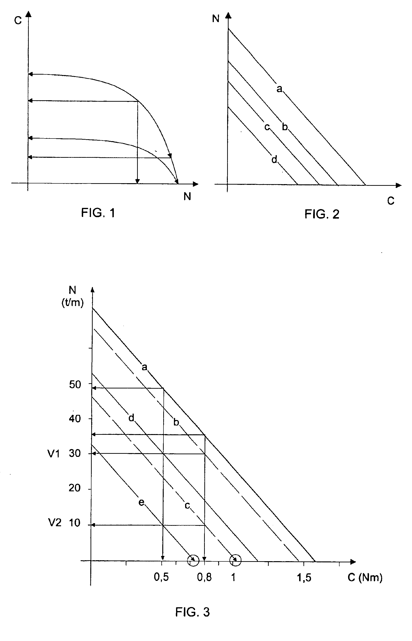
[0024]In the chart represented in FIG. 2, the straight line a diagrammatically represents the shape of the torque / speed characteristic, that is to say of the relation between the torque and the speed for a specified supply voltage. This characteristic is very approximately a straight line. The characteristic shifts parallel to itself when the supply voltage varies. The curves b, c and d correspond to three different supply voltages, the supply voltage decreasing from curve a to curve d.

[0025]In the initial phase, the motor is supplied at the nominal voltage Un. The corresponding characteristic of the motor is represented by the curve a in FIG. 3.

[0026]In the particular supply phase, that is to say the phase of approach to the final position, the supply voltage of the motor is decreased until the speed of the motor is equal to a predetermined value V2, for example 30 rpm. As may be seen in FIG. 3, the operating characteristic of the motor at the speed V2, that is to say its supply v...


PUM


Abstract

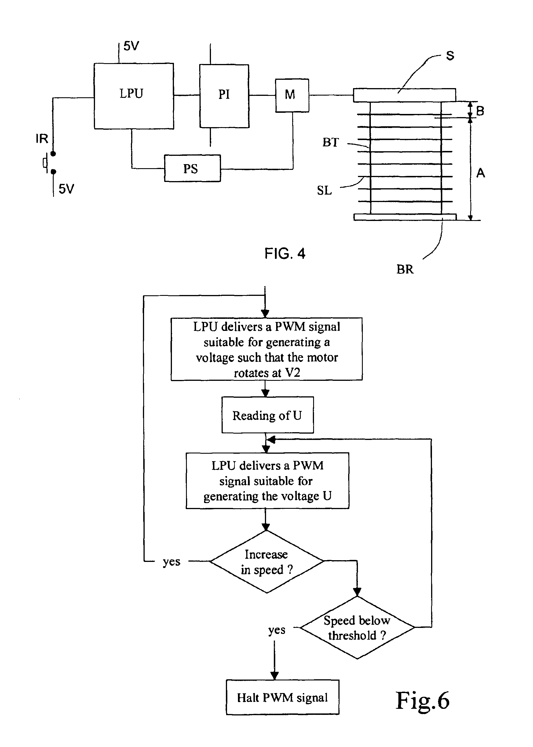
The invention concerns a method for controlling an electric motor driving a body in translation between an initial position and a final position determined by a stop, by powering the motor with reduced voltage in the final position approach phase. The motor has a torque / speed characteristic such that the torque at null speed decreases with the supply voltage. As the approach phase starts, the method consists in determining a reduced voltage by decreasing the rotational speed of the motor from a nominal value to a predetermined reduced value and in cutting the motor power supply if the motor rotational speed drops below a predetermined threshold value.

Description

[0001]This application is a 371 of PCT / IB01 / 01578 filed on Aug. 31, 2001, published on Mar. 21, 2002 under publication number WO 02 / 23005 A1 which claims priority benefits from French patent application number FR 00 / 11812 filed Sep. 15, 2000.BACKGROUND OF THE INVENTION[0002]The subject of the invention is a method of controlling an electric motor driving a body in translation between an initial position and a final position determined by an abutment, according to which the motor is supplied at reduced voltage in the phase of approach to the final position.[0003]The subject of the invention is also a device for the implementation of this method.[0004]The invention relates more particularly to devices for shading and for solar protection such as doors and venetian blinds, arm-mounted blinds, etc.PRIOR ART[0005]Such a method and such devices are known from the patent FR 2 717 016 in the name of the applicant. This patent teaches the instigating of a particular supply phase for the moto...

Claims


Application Information

Patent Timeline
IPC IPC(8): E06B9/82E06B9/80G05B19/19
CPCE06B9/82G05B19/19G05B2219/43071G05B2219/43072G05B2219/43074G05B2219/43077G05B2219/43081G05B2219/43082
Inventor CHERON, ERIC
Owner SOMFY SAS
Learn More