
Mounting rail adapter

a technology for mounting rails and adapters, which is applied in the direction of electrically conductive connections, coupling device connections, electrical apparatuses, etc., can solve the problems of affecting the installation or disassembly of other modules, and achieve the enhancement of the handling of the module and the mounting rail, the effect of facilitating the replacement or mounting of another module, and increasing the flexibility of the overall system

Inactive Publication Date: 2005-08-30
HIRSCHMANN ELECTRONICS GMBH & CO KG
View PDF10 Cites 12 Cited by
  • Summary
  • Abstract
  • Description
  • Claims
  • Application Information

AI Technical Summary

Benefits of technology

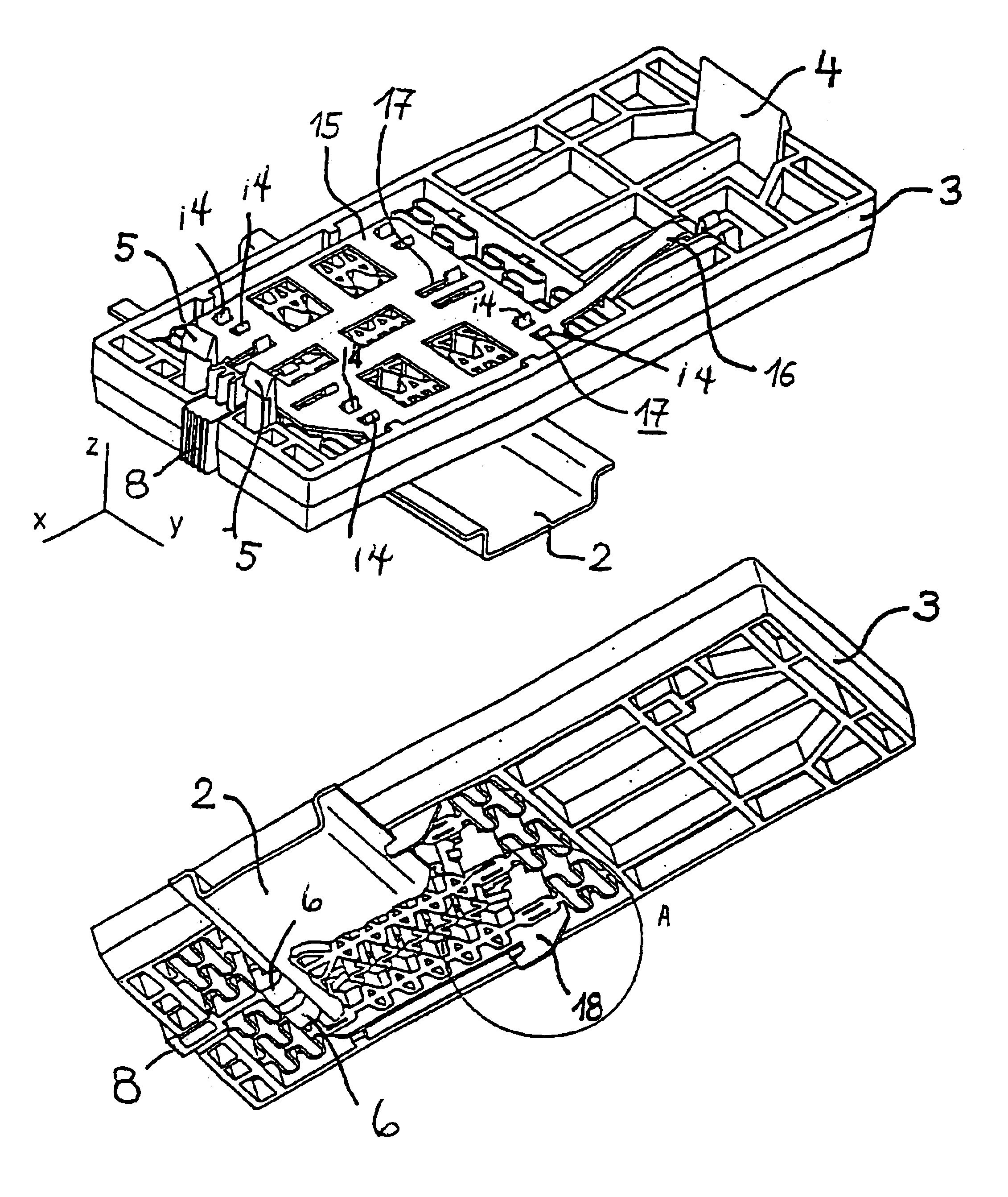
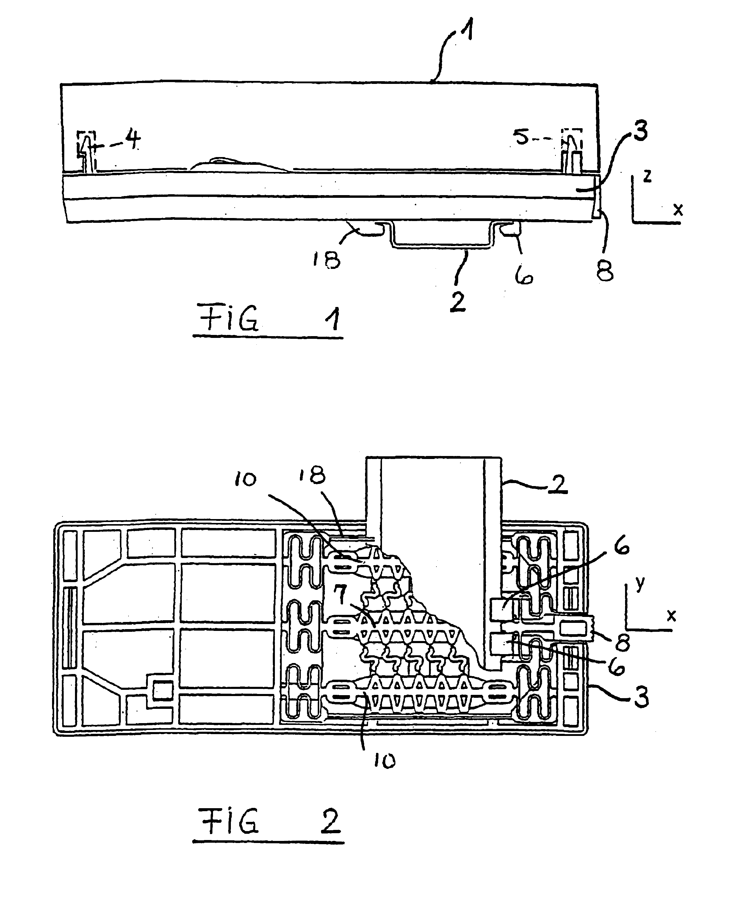
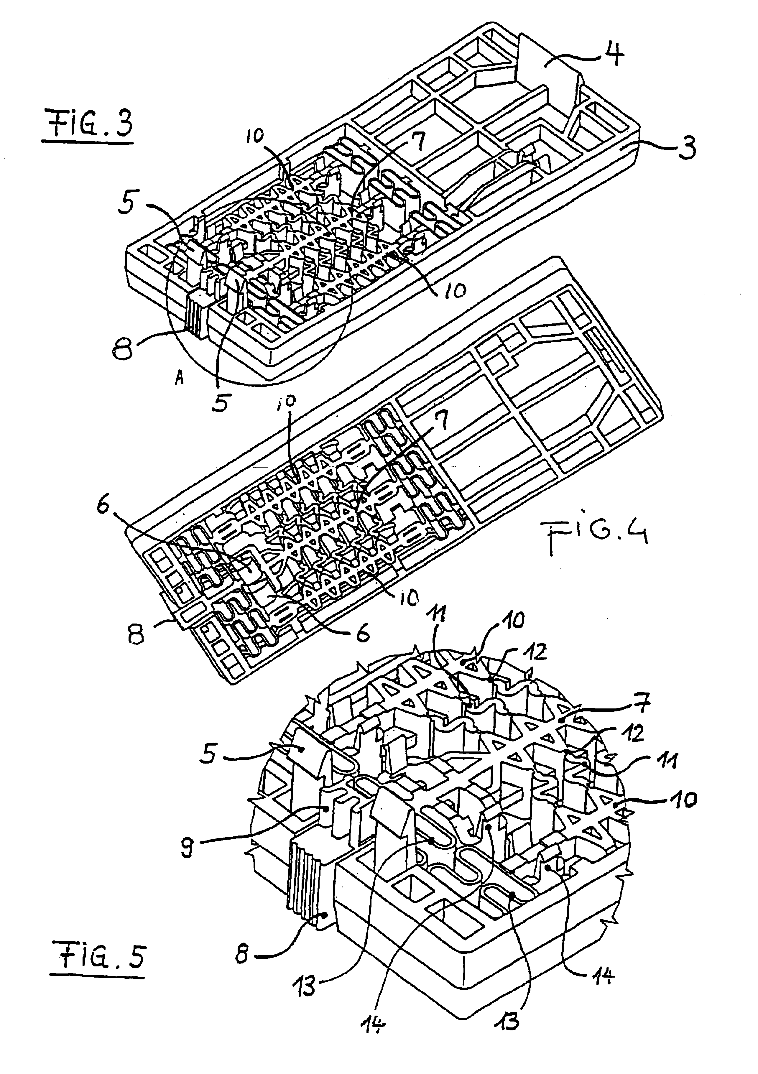
[0005]It is provided as claimed for the invention that modules can be attached via an adapter to a mounting rail. Attachment of the modules via an adapter on the mounting rail has several advantages. On the one hand, the module itself, independently of the mounting rail, can be detached from it and replaced. Thus rapid replacement or mounting of another module is possible for several modules arranged in a row next to one another. On the other hand, the adapter can be made such that after its mounting on the mounting rail it produces an electrical connection to its neighboring adapter or adapters, while likewise there is an electrical connection between the adapter and the mounted equipment module. Thus, when a module is inserted or replaced there are no problems with electrical connections. In this way, when the module is inserted or replaced after it has been detached from the adapter, it can be removed perpendicular to the adapter upwards, by which removal no damage occurs to the electrical connections at all, especially plug connections between an adapter and a module. Alternatively it also is conceivable that the adapter is an integral component of the equipment module and is permanently connected to it, or the equipment module and the adapter form a unit.
[0006]On the other hand, the adapter can be made such that for manual mounting or dismounting a tool is not necessary. This has the advantage that the module can be placed on the mounting rail by hand and can be attached there or vice versa can be detached from the mounting rail by hand. Accordingly, it is not necessary to carry along a tool for mounting or dismounting, by which on the other hand fastening devices for which a tool would be necessary can also be eliminated, thus the simplification of the construction of the modules and handling in their attachment on the mounting rail are enhanced.
[0007]In one development of the invention the adapter has various fastening devices, especially catch devices. On the one hand there are catch devices with which an equipment module is held on the adapter. On the other hand, there are catch devices with which the adapter is held on the mounting rail. These increase the flexibility of the overall system since different adapters can be reserved for different mounting rails and different modules. On the other hand, for uniformly configured catch devices on the adapter and also corresponding catch devices on the module and / or the mounting rail an increased diversity of parts is avoided. The catch devices and the snap connections joined to them again enable that connections between modules and adapters can be made without tools on the one hand and adapters and the mounting rail on the other. The fastening devices also can be screw connections or elements of equivalent type action, combinations also being possible.

Problems solved by technology

On the one hand, the modules can tilt when inserted with their one side edge onto the mounting rail so that easy mounting or dismounting is hindered.
This is a disadvantage with frequent modifications of an electrical device that consists of several equipment modules.

Method used


Image

  • Mounting rail adapter
  • Mounting rail adapter
  • Mounting rail adapter

Examples


Embodiment Construction

[0003]The object of the invention is therefore to improve a modular electrical device like the one described above such that easy mounting or dismounting of equipment modules on a mounting rail is enabled.

[0004]This object is achieved by the features of claim 1.

[0005]It is provided as claimed for the invention that modules can be attached via an adapter to a mounting rail. Attachment of the modules via an adapter on the mounting rail has several advantages. On the one hand, the module itself, independently of the mounting rail, can be detached from it and replaced. Thus rapid replacement or mounting of another module is possible for several modules arranged in a row next to one another. On the other hand, the adapter can be made such that after its mounting on the mounting rail it produces an electrical connection to its neighboring adapter or adapters, while likewise there is an electrical connection between the adapter and the mounted equipment module. Thus, when a module is inser...


PUM


Abstract

The present invention relates to an electrical device with a modular construction, comprising at least one equipment module (1), preferably several equipment modules (1), the module(s) being fixed onto a mounting rail (2). To mount or dismount a module (1) from a mounting rail (2) in a simple manner, the module (1) is fixed onto an adapter (3) for mounting on the mounting rail (2). The adapter (3) for one embodiment fulfills its fixing function by use of a bistable snap-on process and is configured in such a way that no tool is required for the manual mounting or dismounting process. This adapter (3) includes an actuator button (8) used to move catch hooks (5) against spring forces to enable mounting and dismounting of the equipment module (1) to the adapter (3) and also to move catch hooks (18) or (23) to enable mounting and dismounting of adapter (3) to the mounting rail (2).

Description

TECHNICAL DOMAIN[0001]The invention relates to a modular electrical device which has at least one equipment module, preferably several modules, and at least one module can be mounted on a mounting rail, according to the features of the preamble of claim 1.PRIOR ART[0002]A modular electrical device is known from EP 0 527 247 B1. Such a device consists of several modules which can be electrically connected between one another and which modules are matched to the respective application. One application is electrical controls, especially memory-programmable controls. To match such a device to the respective application, it is necessary to interconnect a certain number of equipment modules which can be controls, sensors, and / or actuators. For this purpose EP 0 527 247 B1 discloses a flat mounting rail which is angled on its side edges and on which the modules with their one side edge are suspended and are fixed on the opposite side edge on the mounting rail via a screw connection. This t...

Claims


Application Information

Patent Timeline
Patent Type & Authority Patents(United States)
IPC IPC(8): H02B1/052H02B1/015H05K7/12
CPCH02B1/052Y10S439/953
Inventor GAIDOSCH, OTHMAR
Owner HIRSCHMANN ELECTRONICS GMBH & CO KG
Learn More