Breakwater

Inactive Publication Date: 2005-08-30
DEMPSTER HARRY EDWARD
View PDF45 Cites 60 Cited by
  • Summary
  • Abstract
  • Description
  • Claims
  • Application Information

AI Technical Summary

Benefits of technology

[0004]The present invention addresses this problem by providing a breakwater that can be easier and less expensive to build, and often can be constructed in one location and then towed to a desired use site and installed there.

Problems solved by technology

However, such a breakwater typically is difficult and expensive to build.

Method used


Image

  • Breakwater
  • Breakwater
  • Breakwater

Examples


Embodiment Construction

)

[0043]The first section of the following disclosure describes a system and an apparatus for fabricating a variable-buoyancy structure, as well as discussing the configuration of the final structure itself. Subsequent sections describe various applications in which such a variable-buoyancy structure may be utilized.

Fabricating Technique and Platform

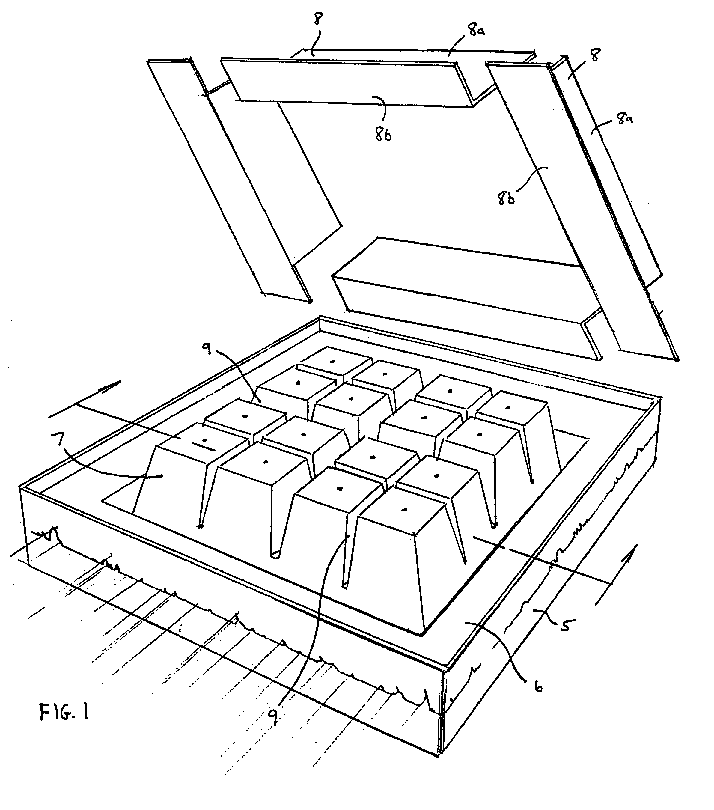
[0044]FIG. 1 is a perspective view of a floating platform 5, having a top surface 6 upon which a mold can be formed for constructing an anchor or other variable-buoyancy structure according to the present invention. Preferably, platform 5 itself has variable buoyancy, allowing it to be submerged and then re-floated. This variable buoyancy may be achieved by installing an array of ballast tanks (e.g., bolted to a series of trusses) underneath surface 6, e.g., in a manner similar to how a conventional dry dock is constructed.

[0045]As shown in FIG. 1, platform 5 has a generally flat top surface 6 upon which an array of forming cells 7 are at...


PUM


Abstract

Provided are static and free-floating breakwater apparatuses that utilize a rocking panel (or beach) to dissipate wave energy. At the same time, such rocking motion can in certain embodiments be used to generate electrical power. Generally speaking, the breakwater apparatuses use a buoyant element, such as an open-bottomed hollow chamber and / or a ballast tank to resist the wave's force.

Description

BACKGROUND OF THE INVENTION[0001]Priority is claimed to U.S. Provisional Patent Application Ser. No. 60 / 454,665, filed on Mar. 17, 2003, and titled “Ocean Wave / Wind Driven Electrical Generating System”, which application is incorporated by reference herein as though set forth herein in full.FIELD OF THE INVENTION[0002]The present invention pertains to a breakwater for dissipating ocean wave energy and / or for converting such energy into electrical power.DESCRIPTION OF THE RELATED ART[0003]A breakwater is an offshore structure for protecting a harbor or beach from the force of waves. The most common type of conventional breakwater is a wall that has been constructed in the ocean. However, such a breakwater typically is difficult and expensive to build.SUMMARY OF THE INVENTION[0004]The present invention addresses this problem by providing a breakwater that can be easier and less expensive to build, and often can be constructed in one location and then towed to a desired use site and in...

Claims


Application Information

Patent Timeline
IPC IPC(8): E02B3/06B63B35/44F03B13/18
CPCB63B35/44E02B3/06F03B13/1815F05B2210/16F05B2210/18Y02E10/38Y02E10/30Y02A10/11
Inventor DEMPSTER, HARRY EDWARD
Owner DEMPSTER HARRY EDWARD
Why Eureka
Try Eureka