
Nano-based device and method

Inactive Publication Date: 2007-05-10
SCHLUMBERGER TECH CORP +1
View PDF11 Cites 7 Cited by
  • Summary
  • Abstract
  • Description
  • Claims
  • Application Information

AI Technical Summary

Benefits of technology

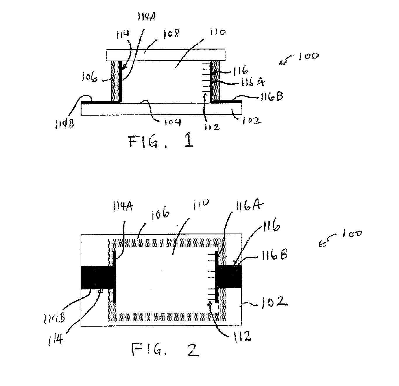
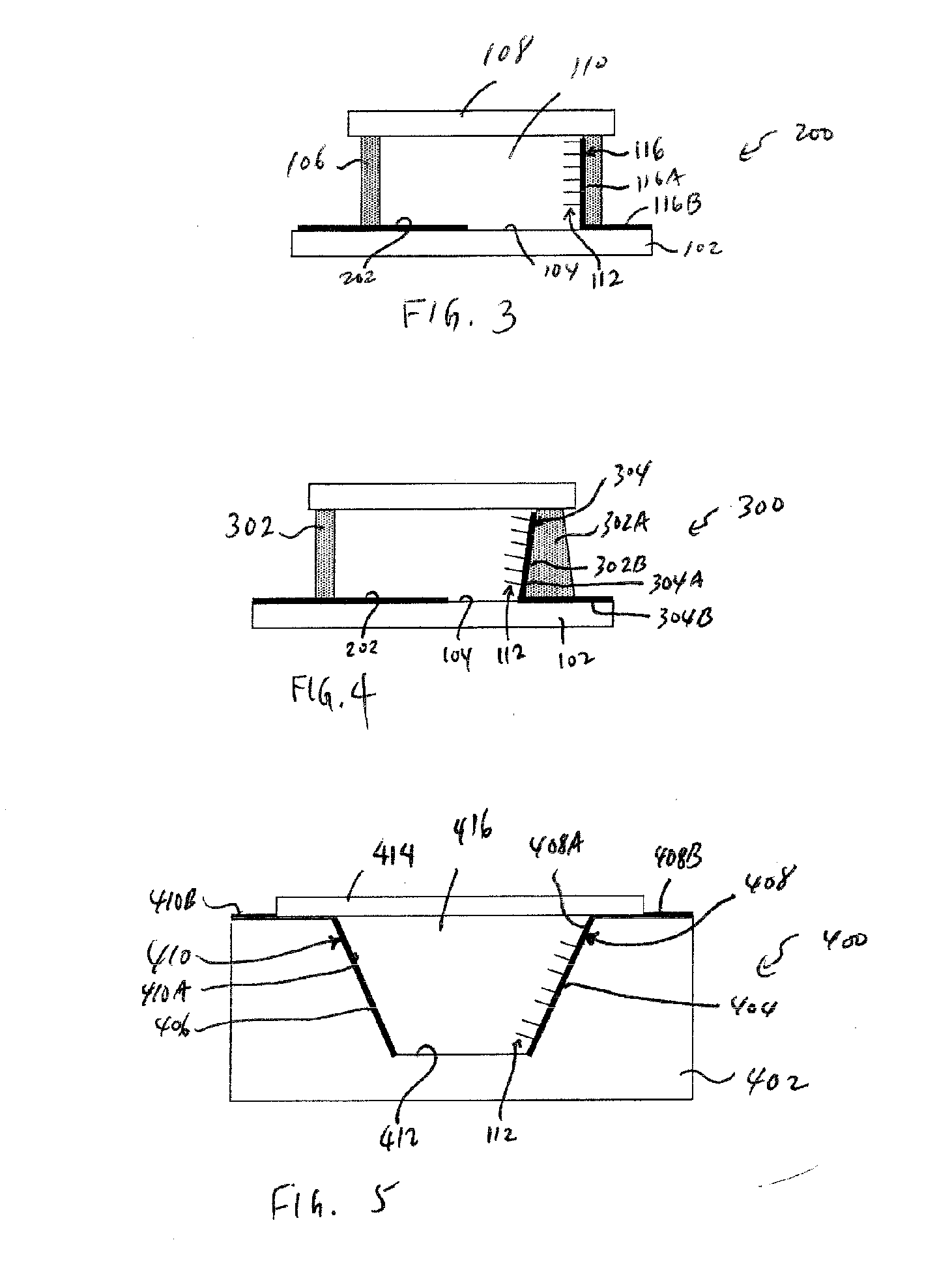
[0004] In general, according to some embodiments, a nano-based device has certain elements (e.g., nano-emitters of electrons) arranged in a planar or horizontal manner to enhance the ability to manufacture such a nano-based device in an efficient manner. In one example, a nano-based device includes a support structure providing a support surface, a second structure providing a second surface angled with respect to the support surface, and at least one nano-emitter provided on the second surface.

Problems solved by technology

Although carbon nanotubes are recognized as providing electrical characteristics that are efficient for forming diodes or switches, conventional diodes or switches that contain carbon nanotubes do not lend themselves to efficient or reliable manufacturing.
Consequently, without devices that can be efficiently and reliably manufactured, cost efficient devices that employ carbon nanotubes are typically not available.

Method used


Image

  • Nano-based device and method
  • Nano-based device and method
  • Nano-based device and method

Examples


Embodiment Construction

[0015] In the following description, numerous details are set forth to provide an understanding of the present invention. However, it will be understood by those skilled in the art that the present invention may be practiced without these details and that numerous variations or modifications from the described embodiments may be possible. As used here, the terms “horizontal” and “vertical” are used to indicate relative positions of components depicted in the various figures. Note, however, that the devices illustrated in the figures can have orientations different from the orientations of the figures when in actual use. Thus, dependent upon the actual orientation of any described device when in actual use, the terms “horizontal” and “vertical” can refer to different orientations. The terms “horizontal” and “vertical” are intended to refer to relative orientations but can have different meanings when devices are in actual use. For example, “horizontal” can refer to a vertical orienta...


PUM


Abstract

A nano-based device includes a support structure providing a support surface, a second structure providing a second surface angled with respect to the support surface, and at least one nano-emitter provided on the second surface.

Description

TECHNICAL FIELD [0001] The invention relates generally to nano-based devices, such as nano-diodes or nano-switches. BACKGROUND [0002] Nanotechnology has become increasingly popular as a technique for fabricating various types of devices, such as diodes and switches. One type of element that has been studied for making nanotechnology-based devices is the carbon nanotube, which is a cylindrical carbon structure that exhibits certain desirable electrical properties. [0003] Although carbon nanotubes are recognized as providing electrical characteristics that are efficient for forming diodes or switches, conventional diodes or switches that contain carbon nanotubes do not lend themselves to efficient or reliable manufacturing. Consequently, without devices that can be efficiently and reliably manufactured, cost efficient devices that employ carbon nanotubes are typically not available. SUMMARY OF THE INVENTION [0004] In general, according to some embodiments, a nano-based device has cert...

Claims


Application Information

Patent Timeline
IPC IPC(8): H01L21/00
CPCB82Y10/00H01L29/0665H01L29/0673H01L29/861E21B43/00H01J1/304H01J9/02H01J9/025
Inventor VENERUSO, ANTHONY F.ULLO, JOHNGEREZ, DAVIDWEI, BINGQINGKRISHNA, ABHILASH
Owner SCHLUMBERGER TECH CORP
Learn More