
Diesel engine

a technology of diesel engine and engine body, which is applied in the direction of machines/engines, liquid fuel feeders, electric control, etc., can solve the problems of engine instability, reduced fuel injection rate, and general instability of diesel engine ignitability, so as to prevent the generation of white smoke. favorable

Inactive Publication Date: 2005-08-30
KOMATSU LTD
View PDF10 Cites 5 Cited by
  • Summary
  • Abstract
  • Description
  • Claims
  • Application Information

AI Technical Summary

Benefits of technology

[0007]An object of the present invention is to provide a diesel engine capable of favorably preventing the generation of white smoke even when an engine load is shifted from a high load side to a low load side.
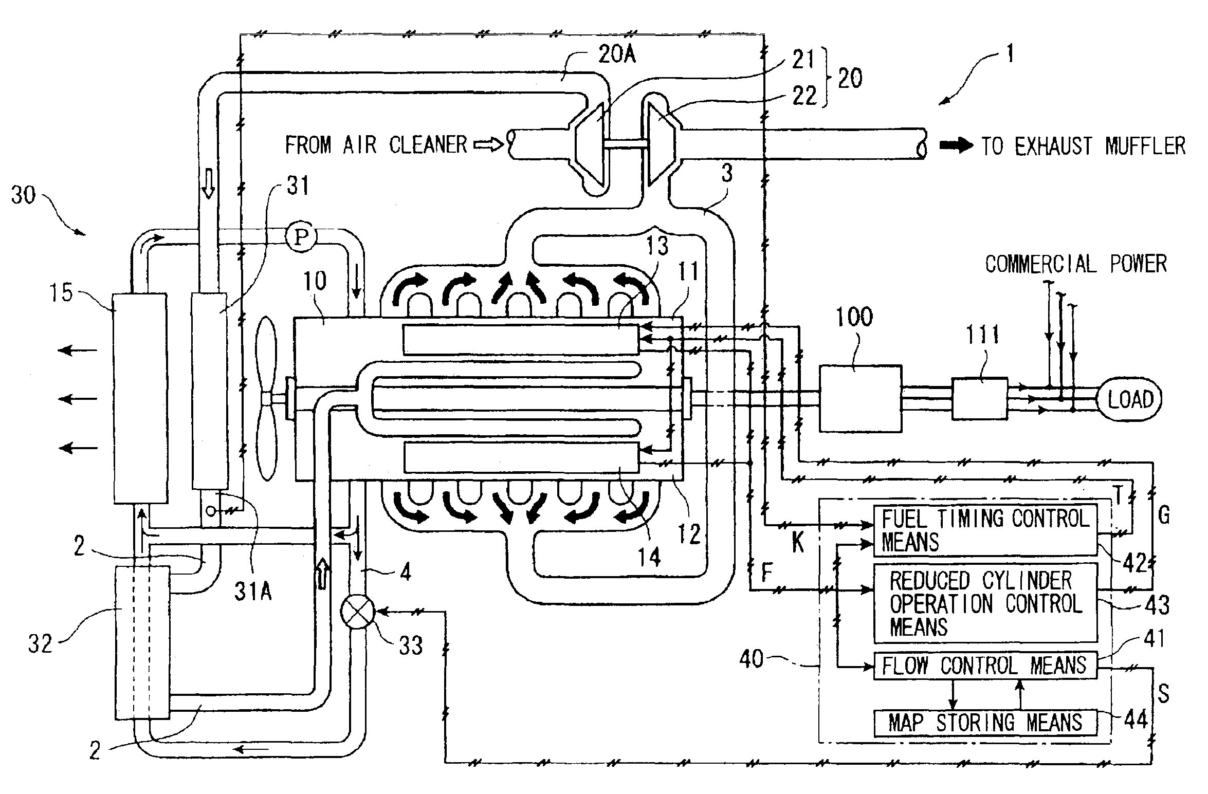
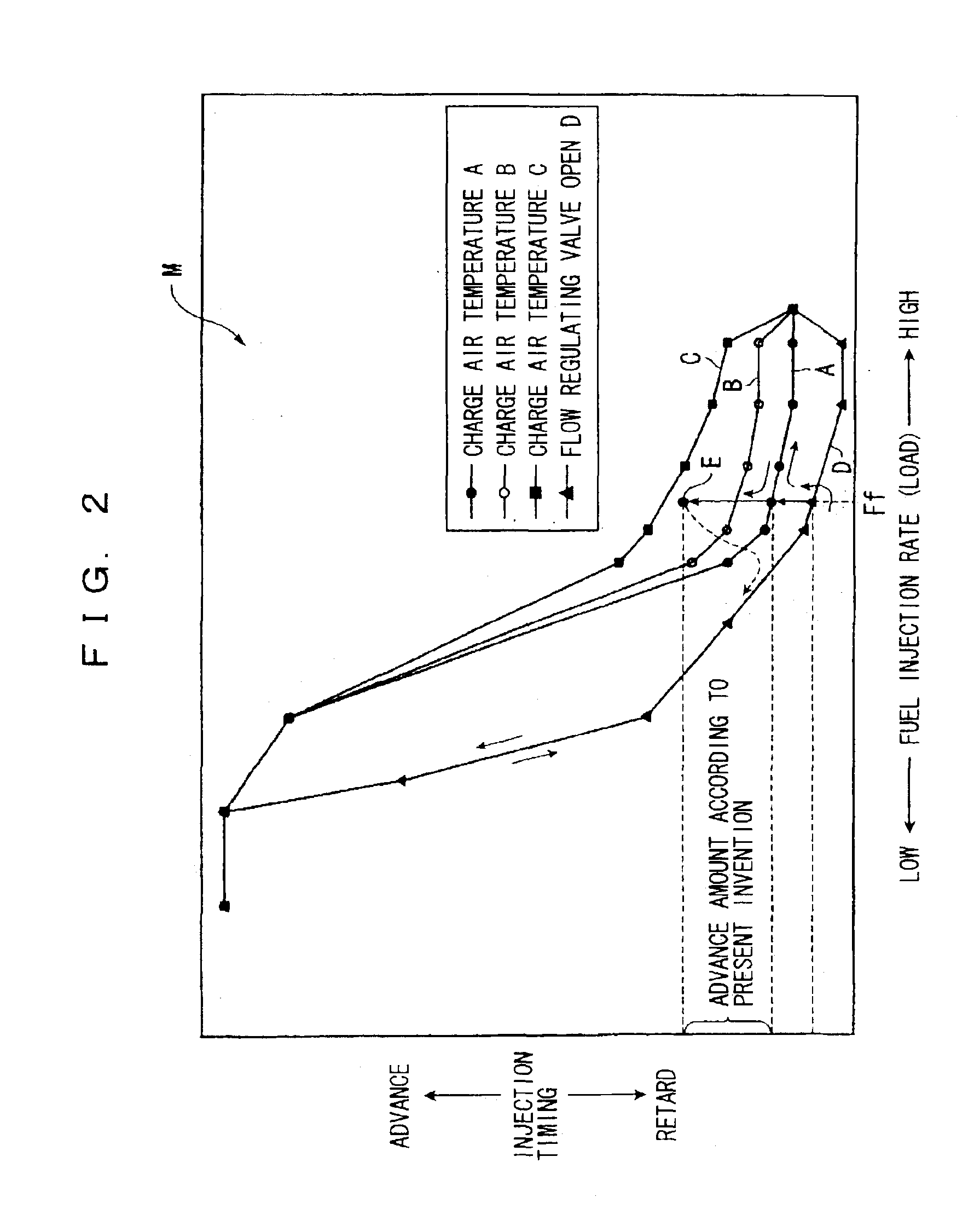
[0009]In the above constitution, when the engine load becomes the predetermined load or lower during the engine stopping step, the fuel injection timing is advanced by the fuel injection timing control means. Consequently, even under a low load with a low fuel injection rate, more fuel is injected until ignition by the amount provided by advancing the fuel injection timing to improve ignitability and enhance combustion efficiency at the time of ignition, and the generation of white smoke is curbed.

Problems solved by technology

However, when the load is shifted from a high load side to a low load side, the diesel engine generally becomes unstable in its ignitability with the fuel injection rate being reduced, irrespective of the presence or absence of a supercharger and heat exchanging means.
For this reason, for example, when a diesel engine is used to drive a motor and the like, the engine has more unstable ignitability and easily generates while smoke in an engine stopping step in which the load continues to be reduced to stop the engine while the engine speed is kept constant, and the fuel injection rate continues to be reduced following this.
The above problem is prominent especially when a fuel with low ignitability such as an emulsion fuel is used, and when the engine load is below a predetermined engine load, a non-combusted fuel increases due to reduction in ignitability, thus easily generating white smoke.
However, in this situation, the second heat exchanger is cooled with charge air at a low temperature, which circulates under the high load, and therefore the heat of the second medium is depleted by (the metal components and the like of) the second heat exchanger itself.
Thus, the second heat exchanger is not sufficiently heated, and it cannot warm the charge air immediately.

Method used


Image

  • Diesel engine
  • Diesel engine
  • Diesel engine

Examples


Embodiment Construction

[0022]An embodiment of the present invention will be explained hereinafter based on the drawings.

[0023]FIG. 1 is a block diagram showing a schematic constitution of a diesel engine 1 according to the present embodiment. The diesel engine 1 is installed in a power generating system placed in a factory, a building, a large store or the like, and is used as a driving source of a generator 100 for a three-phase alternating current. A fuel is not especially limited, and a water emulsion fuel (water content of 50%) with lower ignitability as compared with light oil is used in this embodiment. Methanol, fuel oil A, a waste plastic fuel and the like can be also used other than the above as the fuel with low ignitability. The diesel engine 1 is a so-called V type engine and a water cooling type including a supercharger 20.

[0024]Accordingly, an engine main body 10 of the diesel engine 1 includes a first bank 11 and a second bank 12 separated at suitable banking angles, and the banks 11 and 12...


PUM


Abstract

A diesel engine capable of favorably preventing the generation of white smoke even when an engine load is shifted from a high load side to a low load side. For this purpose, a diesel engine (1) includes fuel injection timing control means (42) for controlling fuel injection timing, the fuel injection timing control means (42) advances the fuel injection timing by predetermined time when an engine load becomes a predetermined load (Ff) or lower in an engine stopping step of stopping the diesel engine while gradually reducing the engine load.

Description

TECHNICAL FIELD[0001]The present invention relates to a diesel engine.BACKGROUND ART[0002]Various means for reducing NOx and reducing fuel consumption under a high load, and curbing the generation of white smoke under a low load are developed in a diesel engine having a supercharger (hereinafter, simply abbreviated as an engine in some cases). As such means, the one in which heat exchanging means is provided between an outlet of a supercharger and a combustion chamber, the heat exchanging means is constituted of a first heat exchanger at an upstream side and a second heat exchanger at a downstream side, a first and a second media having different temperatures are used for heat exchange in the first and the second heat exchangers, and after heat exchange is carried out between these first and second media and charge air, the charge air is fed into the combustion chamber (for example, patent document 1). Here, patent document 1 refers to Japanese Patent Laid-open No. 2001-342838, and ...

Claims


Application Information

Patent Timeline
IPC IPC(8): F02D41/12F02D41/00F02D41/32F02D41/36F02D41/40F02D41/04F02D17/02F01P3/20F01P7/16F02D19/08F02D41/30
CPCF02D41/0007F02D41/0087F02D41/042F02D41/12F02D41/401F02D2200/0414Y02T10/44Y02T10/144Y02T10/12Y02T10/40
Inventor WATANABE, KINICHIROUSAKASAI, TAKASHINAGASAKA, SHOUHEI
Owner KOMATSU LTD
Learn More