
Anti-bob system for cycles

a technology of anti-bob system and cycle, which is applied in the field of pedal-powered cycles, can solve the problems of inability to provide the inherent flexibility of the frame of the cycle, requiring constant user input, and wasting energy on the part of the rider

Inactive Publication Date: 2005-08-30
THE LARRY D MILLER TRUST LARRY D MILLER & MARY L MILLER TRUSTEES DTD 06 12 98
View PDF17 Cites 114 Cited by
  • Summary
  • Abstract
  • Description
  • Claims
  • Application Information

AI Technical Summary

Benefits of technology

"The patent describes an anti-bob system for controlling a shock damping device on a cycle. The system includes a torque detector that measures the amount of torque applied to the cycle's crank axle and sends a signal to activate the shock damping device. This allows for precise control of the shock damping device based on the level of torque applied. The control signal can be a mechanical or electrical signal, and can be produced by a bearing assembly or a pressure responsive device. The system helps to reduce bobbing (when the cycle bounces) and ensures a smoother ride for the user."

Problems solved by technology

Mountain bikes and other such off-road cycles are often operated under extreme conditions in which severe road shocks are encountered.
While shock damping devices can function efficiently to absorb road shocks, the inherent flexibility which they provide to the frame of the cycle is at times undesirable.
This flexibility presents a particular problem when a rider exerts a high degree of torque on the pedal cranks.
Bobbing results in wasted energy on the part of the rider, since a portion of the rider's energy input is nonproductively absorbed by the shock damping devices.
The problem with devices of this type is that they require constant user input, and do not respond quickly enough to maximize shock damping while minimizing bobbing.
These approaches are expensive, and are very difficult to implement since they require precisely machined parts and / or specially dedicated frames.
In addition, devices of this type are very difficult to maintain, and must generally be tuned for each rider's weight and pedaling characteristics.

Method used


Image

  • Anti-bob system for cycles
  • Anti-bob system for cycles
  • Anti-bob system for cycles

Examples


Embodiment Construction

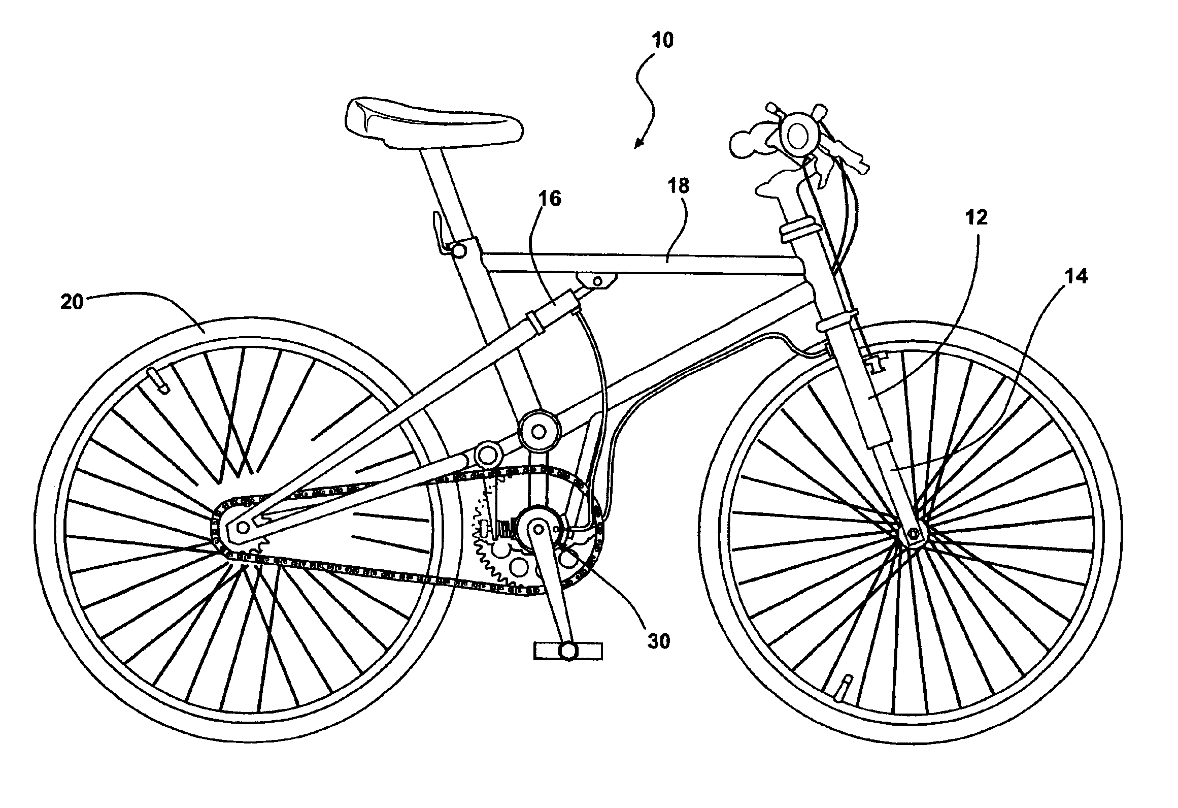
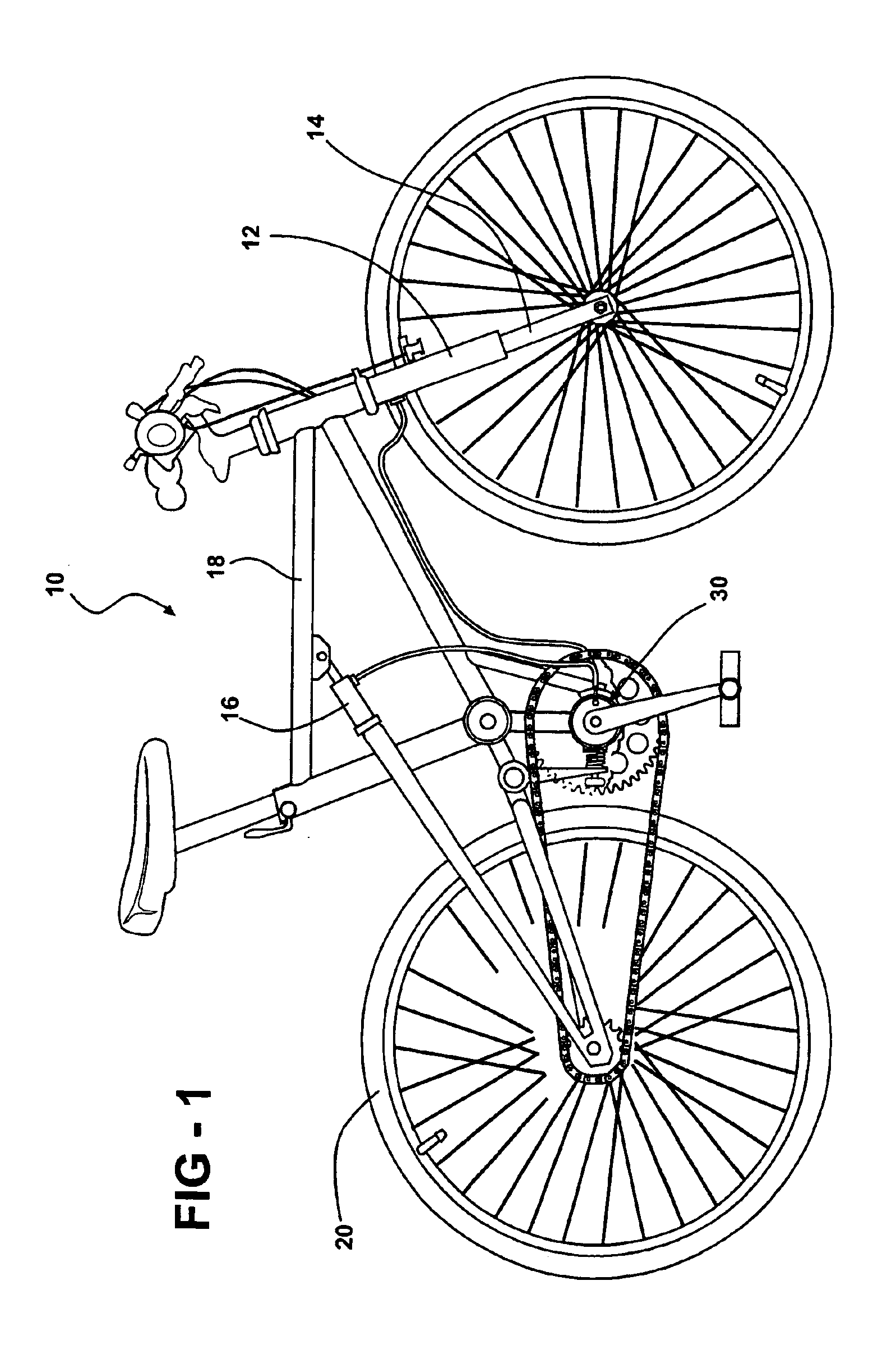
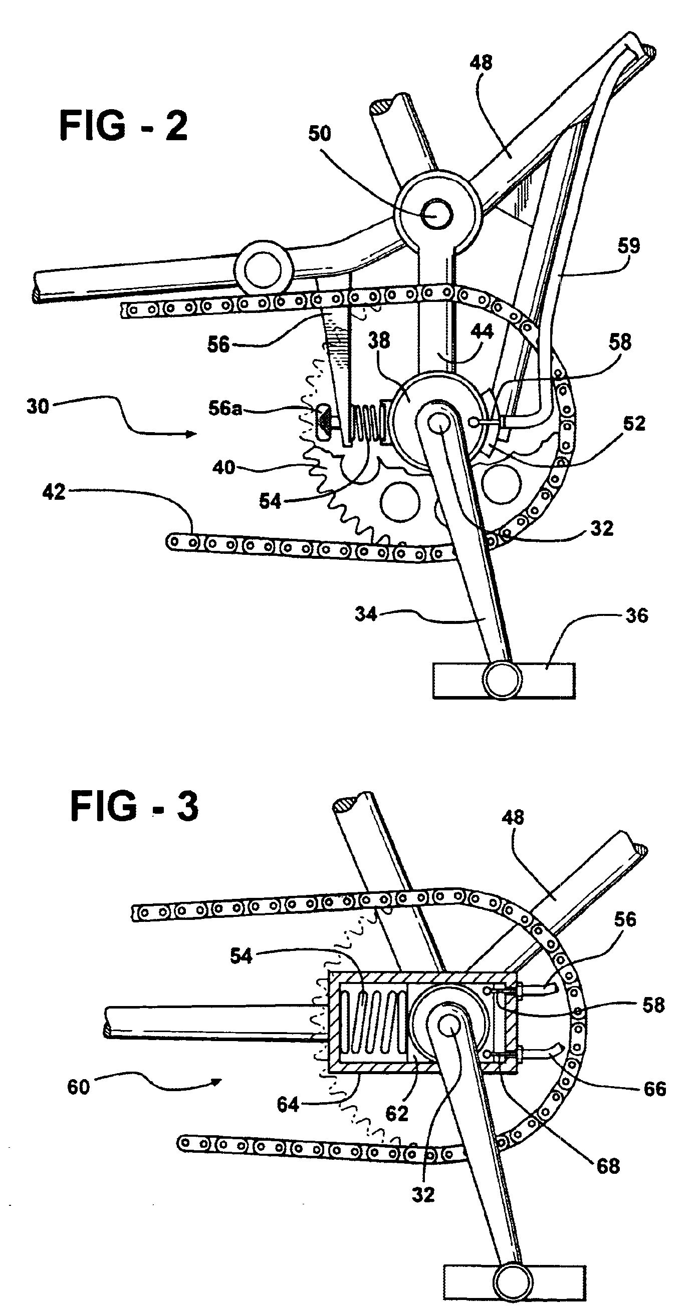
[0016]The present invention comprises an anti-bob system for controlling the shock absorbing devices of a cycle such as a mountain bike. The system includes a simple torque detector which is operable to detect the level of torque applied to the crank axle which drives the cycle. In one embodiment, the detector is directly associated with the crank set, while in other embodiments it may be a pressure responsive device interposed between a user's foot and a pedal of the crank set. The detector produces a control signal, which can be a mechanical signal or an electrical signal. This signal is indicative of the crank axle torque, which occurs when a rider imposes a force on the pedals. This control signal is communicated to, and controls, the activation of a shock damping device. The shock damping devices used in the present invention are controllable shock damping devices as are known in the prior art.

[0017]This control signal activates and deactivates the shock damping device in one e...


PUM

PropertyMeasurementUnit
timeaaaaaaaaaa
torqueaaaaaaaaaa
biasing forceaaaaaaaaaa

Abstract

A control system is operable to selectably activate shock damping devices associated with a bicycle so as to eliminate bobbing encountered under extreme pedaling conditions. The system includes a crank axle torque detector which operates to detect a level of torque applied to a crank axle and provide a control signal corresponding to the level of torque. A shock damping device is coupled to the frame of the cycle, and functions to absorb and dampen mechanical shocks communicated to the frame. The shock damping device includes an activator for controlling its damping function. The activator is operable to receive the control signal from the crank axle torque detector and control the shock damping device in response thereto. The control signal may be an electrical or a mechanical signal.

Description

RELATED APPLICATION[0001]This patent application claims priority of provisional patent application Ser. No. 60 / 417,882 filed Oct. 11, 2002, and entitled “Anti-Bob System for Cycles.”FIELD OF THE INVENTION[0002]This invention relates generally to bicycles and the like. More particularly, the invention relates to pedal-powered cycles. Most specifically, the invention relates to a system for selectively controlling shock damping devices associated with pedal-powered cycles.BACKGROUND OF THE INVENTION[0003]Cycles, which term is understood to include bicycles, tricycles, unicycles and other pedal-powered devices, may include shock damping devices such as shock absorbers for absorbing road shocks which would otherwise be communicated to the cycle frame. Mountain bikes and other such off-road cycles are often operated under extreme conditions in which severe road shocks are encountered. In order to maximize a rider's comfort and minimize dangers of damage to the frame of the cycle, shock d...

Claims


Application Information

Patent Timeline
Patent Type & Authority Patents(United States)
IPC IPC(8): G01M7/00G01L3/00B62JB62K19/34
CPCB62K19/34
Inventor MILLER, LARRY D.
Owner THE LARRY D MILLER TRUST LARRY D MILLER & MARY L MILLER TRUSTEES DTD 06 12 98
Learn More