
Tandem warhead

a technology of tandem warhead and tandem, which is applied in the field of tandem warhead, can solve the problems of heavy casualties and ineffective destruction of targets, and achieve the effect of improving the chance of destroying enemy targets

Inactive Publication Date: 2005-08-23
OL SECURITY LIABILITY CO
View PDF103 Cites 22 Cited by
  • Summary
  • Abstract
  • Description
  • Claims
  • Application Information

AI Technical Summary

Benefits of technology

The invention is a more lethal warhead that can destroy enemy targets carrying chemical or biological payloads. It consists of a kinetic energy rod section and a blast fragmentation section. The kinetic energy rod section is deployed first in the target's trajectory path, and the blast fragmentation section is deployed second, proximate to the target. The kinetic energy rod section includes a plurality of cylindrical or non-cylindrical projectiles with an explosive charge. The method involves deploying the projectiles and initiating the blast fragmentation warhead to destroy any surviving portions of the target.

Problems solved by technology

The fragments of the blast fragmentation type warhead, however, are not always effective at destroying the target and biological bomblets and / or chemical submunition payloads can survive and still cause heavy casualties.

Method used


Image

  • Tandem warhead
  • Tandem warhead
  • Tandem warhead

Examples


Embodiment Construction

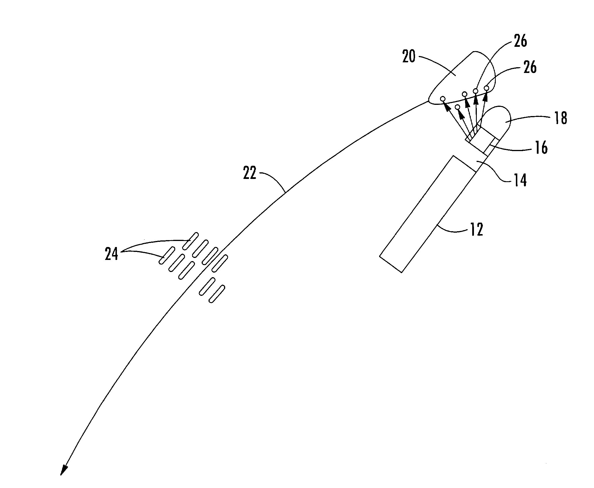
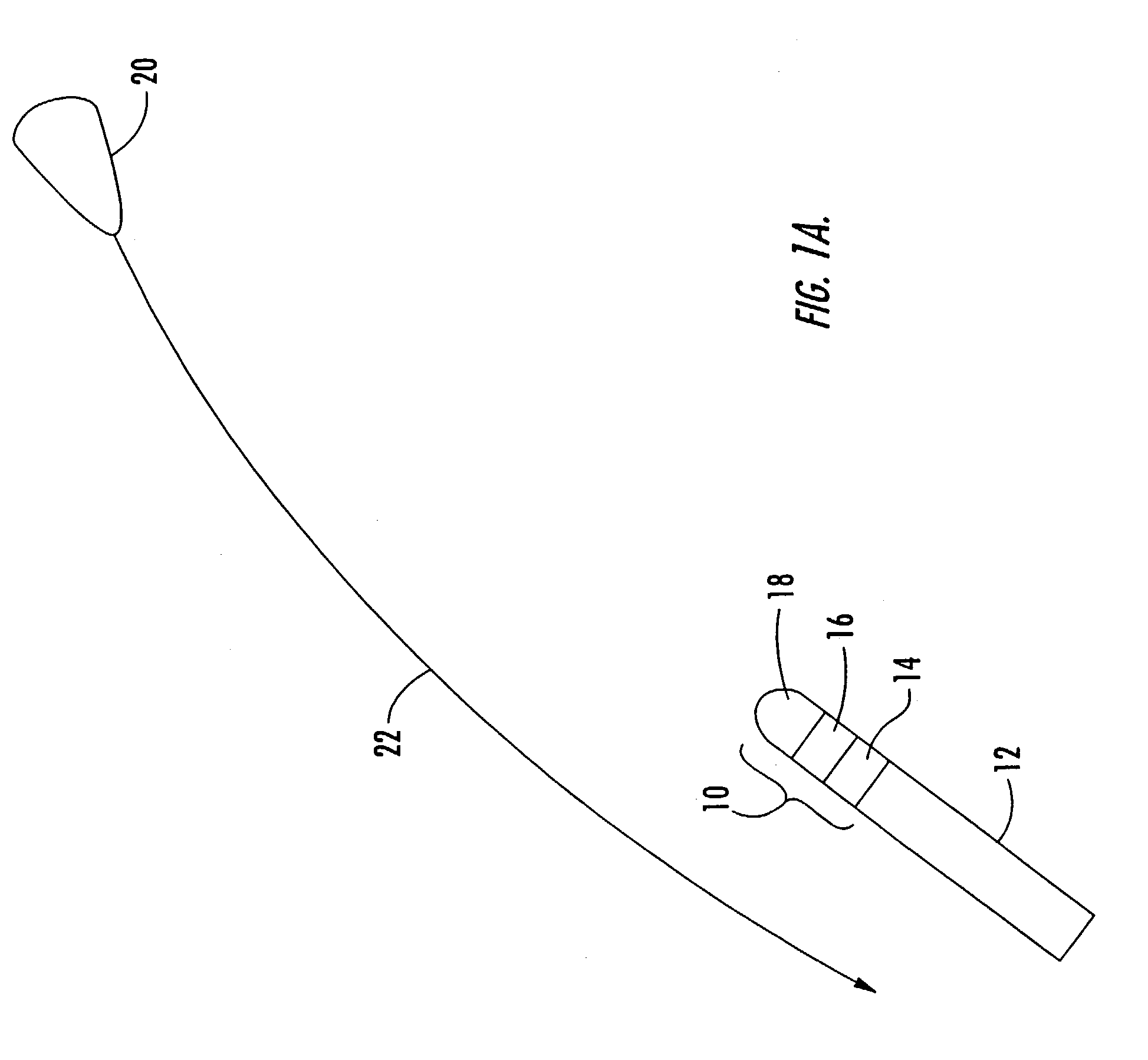
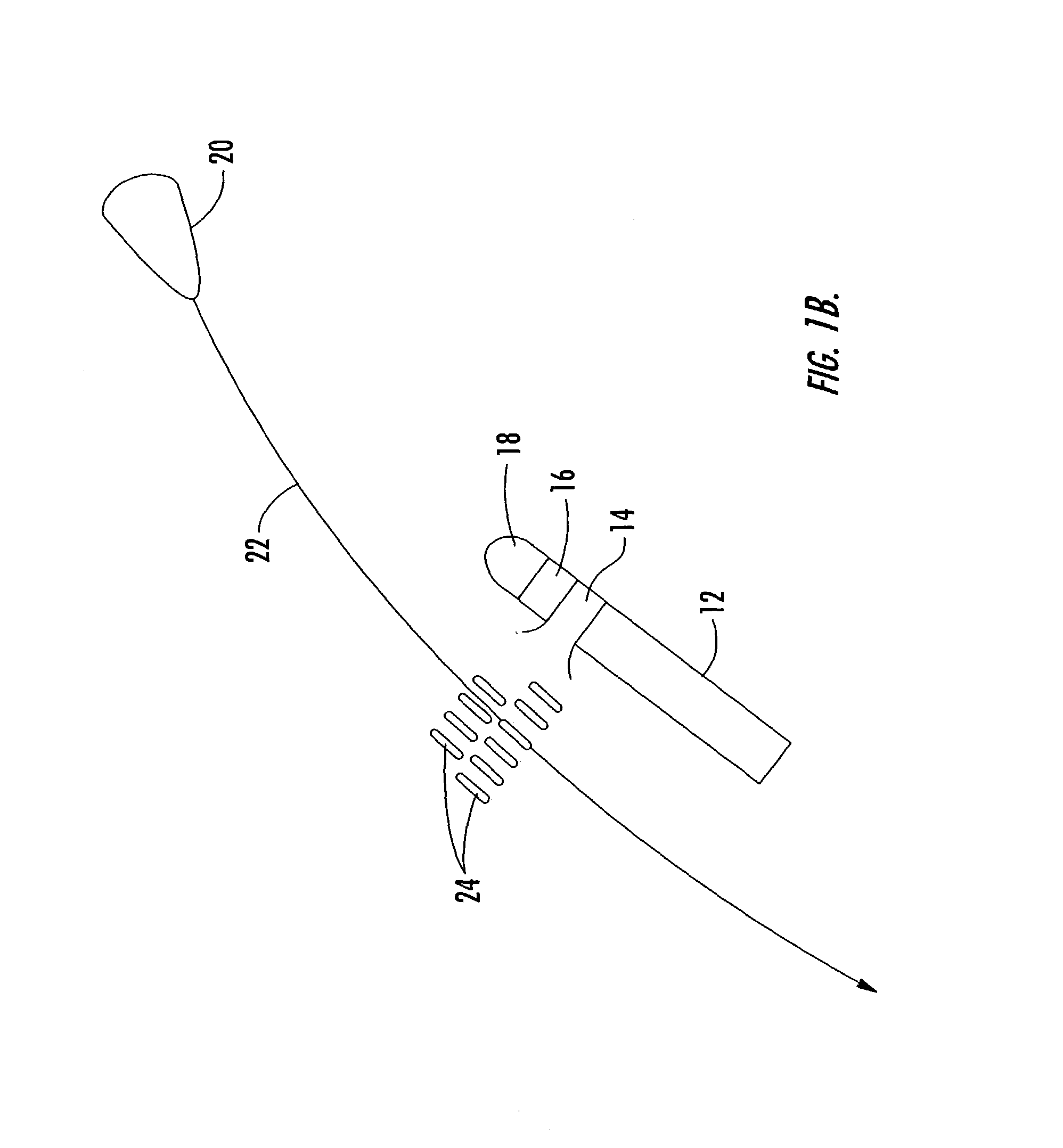
[0015]Tandem warhead 10, FIG. 1A carried by missile 12 and including kinetic energy rod section 14, blast fragmentation section 16, and guidance subsystem 18, is shown nearing target 20 having trajectory path 22. In FIG. 1B, guidance subsystem 18 serves as one means for initiating the deployment of kinetic energy rod section 14 deploying lengthy titanium, tantalum, or tungsten projectiles 24 in the trajectory path 22 of target 20 and then guidance subsystem 18 continues to guide missile 12 proximate target 20, FIG. 1C whereupon blast fragmentation section 16 is deployed and blast fragments 26 thereof strike target 20.

[0016]As shown in FIG. 1D, however, target 20 is not completely destroyed by blast fragmentation warhead 16 and submunitions 30 have survived the blast fragmentation engagement. But, projectiles 24 lie in the trajectory path of the submunitions and they are destroyed by projectiles 24 as shown in FIG. 1E.

[0017]The result is a much more lethal warhead combining the letha...


PUM


Abstract

A tandem warhead for destroying a target, the tandem warhead including a kinetic energy rod section with a plurality of lengthy individual projectiles, a blast fragmentation section deployable proximate the target, and a guidance subsystem for deploying the projectiles of the kinetic energy rod section first in the trajectory path of the target and for deploying the blast fragmentation section second proximate the target.

Description

[0001]This application claims priority of U.S. Provisional Patent Application Ser. No. 60 / 406,828 filed Aug. 29, 2002.FIELD OF THE INVENTION[0002]This invention relates to a tandem warhead with kinetic energy rod warhead and blast fragmentation warhead sections.BACKGROUND OF THE INVENTION[0003]A blast fragmentation type warhead is designed to be carried by a missile and is used to destroy enemy missiles, aircraft, re-entry vehicles, and other targets. When the missile carrying the warhead reaches a position close to an enemy missile or other target, a pre-scored or pre-made band of metal on the warhead is detonated and pieces of metal are accelerated with high velocity and strike the target. See the textbook by the inventor hereof, R. Lloyd, “Conventional Warhead Systems Physics and Engineering Design,” Progress in Astronautics and Aeronautics (AIAA) Book Series, Vol. 179, ISBM 1, 56347-255-4, 1998, incorporated herein by this reference, which provides additional details on conventi...

Claims


Application Information

Patent Timeline
Patent Type & Authority Patents(United States)
IPC IPC(8): F42C19/00F42C19/095F42B12/32F42B12/58F42B12/60F42B12/64F42B12/02F41H13/00F41H11/00F41H11/04F42B12/20F42B12/22
CPCF42B12/205F42B12/22F42B12/60F42B12/64
Inventor LLOYD, RICHARD M.
Owner OL SECURITY LIABILITY CO
Learn More