
Method of forming a wire package

Inactive Publication Date: 2005-08-23
LIAO CHASE
View PDF14 Cites 1140 Cited by
  • Summary
  • Abstract
  • Description
  • Claims
  • Application Information

AI Technical Summary

Benefits of technology

[0010]Still another object of the present invention is to control the width of each wire used in making a wire package by deforming each and making a plurality of flat sides.

Problems solved by technology

As a result of this manufactured process, the bonding strength between each wire in a package is weak.
The inherent failure causes a weak glue line and eventually causes the package of brads or staples to fall apart in the hands of the consumer during installation, Moreover, the user must then force the separated staples or wires into a feeder eventually leading to jamming or misfeed.
Sometimes these jams result in destruction of the feeding unit.
A further problem inherent in producing round wires for brads or staples is width control.
The tolerances are critical for size or width of a wire which fits in a fastener gun and the drawing process now required to meet these limitations is expensive and time consuming.

Method used


Image

  • Method of forming a wire package
  • Method of forming a wire package
  • Method of forming a wire package

Examples


Embodiment Construction

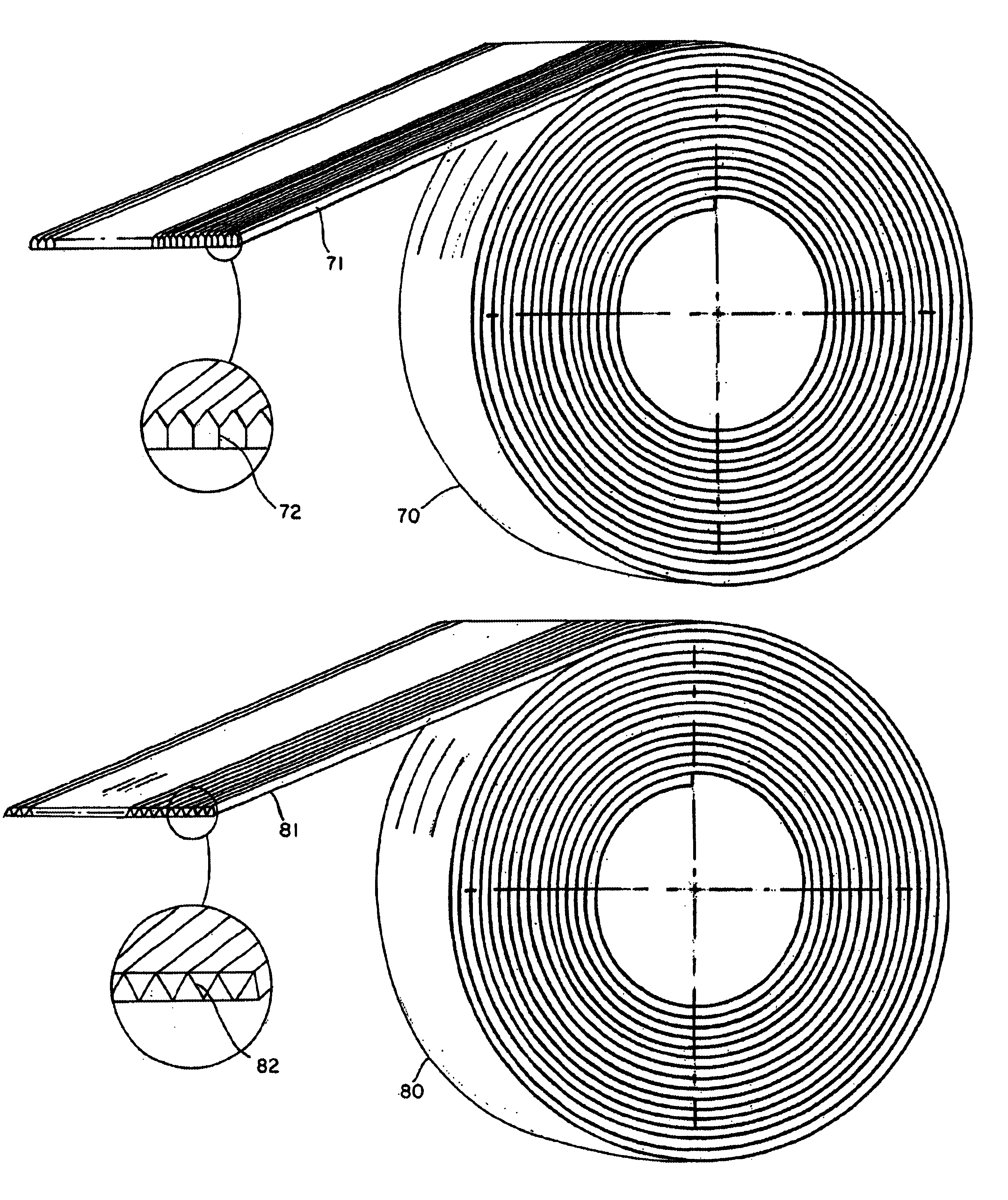
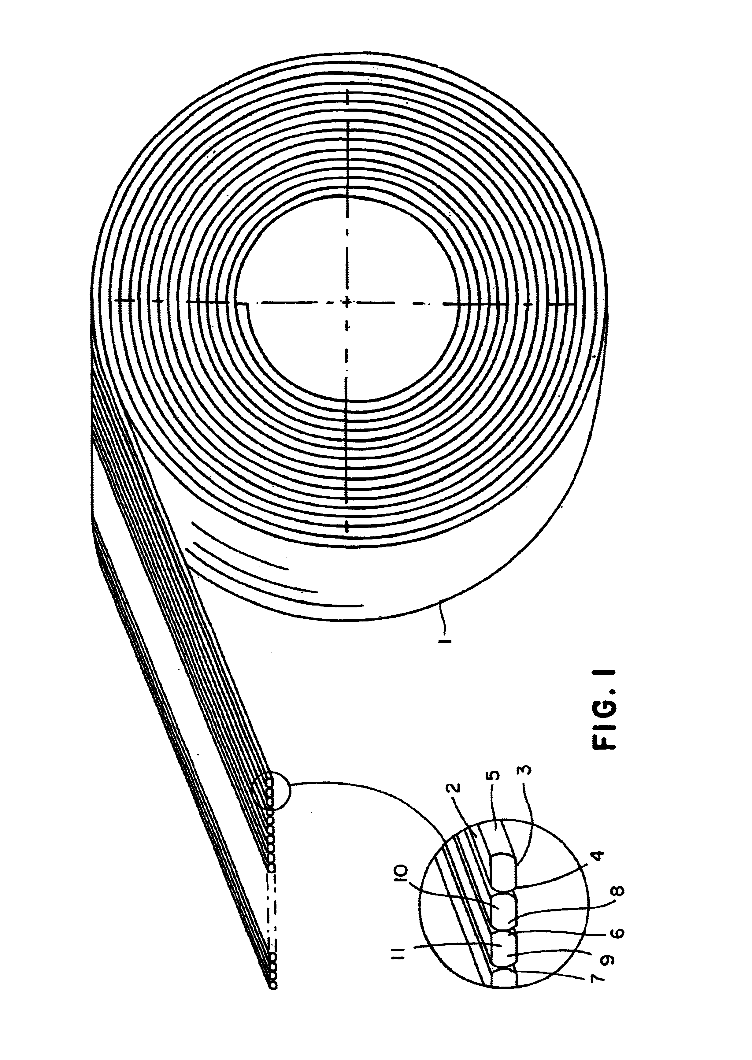
[0023]A novel method of making a package of wire brads or divergent staples is disclosed and illustrated in FIGS. 2-10 and described in the present application. FIG. 1 illustrates a prior art wire package 1 drawn and formed into a brad or a staple package. A round wire is drawn and deformed to produce two flat sides 2, 3 and two round sides 4, 5. The round sides 6 and 7 are bonded to round sides 8, 9 of adjacent wires 10, 11 to form the package 1. The bonding at the center of the curve of the wire fails to provide adequate contact area.

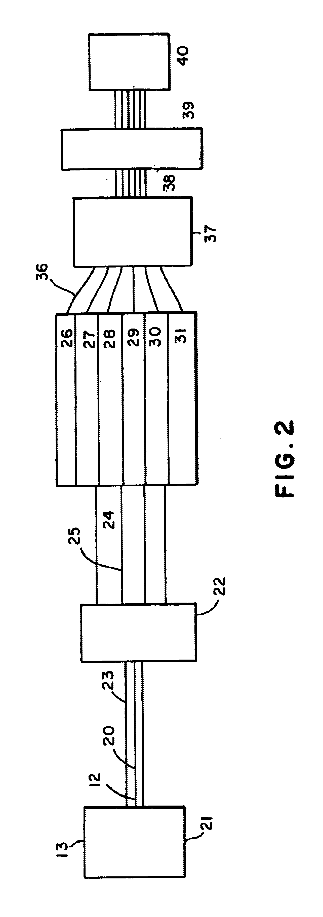
[0024]A method of making a wire package is schematically shown inFIG. 2. A plurality of round wires 12 are drawn from a well known drawing apparatus 13 for producing round wires 14. Each wire 20 is formed of metal such as copper, steel, stainless steel, or titanium. As many as 2-200 wires at a time could be drawn from the wire drawing apparatus. In order to form the size of the wire 20 to the selected width, the techniques used in the drawing process ...


PUM


Abstract

A method for making a wire package for use as staples or brads is recited as forming a plurality of round wires, forming a plurality of flattened bonding sides on each wire to prepare even bonding surfaces on each wire and bonding each wire to an adjacent wire by adhering the surfaces of each wire. Each staple includes two or more flat surfaces to improve the bonding strength of each staple. A package of diverging staples or brads are formed using the flat bonding surfaces

Description

BACKGROUND OF THE INVENTION[0001]Staples and brads for manual, pneumatic and electrical tools are all made by drawing wires and forming two flat sides on each wire. The force that flattens the wire is applied to opposite sides of the wire simultaneously to form two flat surfaces and two round surfaces opposite each other.[0002]Each round side is used to attach each wire to the next wire to form a package by adhesively bonding the round sides. The flat sides are not used as the bonding surfaces. The bonding is performed by adhesives well known in the art.[0003]As a result of this manufactured process, the bonding strength between each wire in a package is weak. The line of contact between each round side of each wire is at the apex point on the curve created by each round side. The inherent failure causes a weak glue line and eventually causes the package of brads or staples to fall apart in the hands of the consumer during installation, Moreover, the user must then force the separat...

Claims


Application Information

Patent Timeline
IPC IPC(8): B21F45/24B21F45/00
CPCB21F45/24
Inventor LIAO, CHASE
Owner LIAO CHASE
Learn More