
Electromechanical switching device

a switching device and electromechanical technology, applied in the direction of electrochemical generators, safety/protection circuits, instruments, etc., can solve the problems of serious damage to either or both vehicles' electrical systems, and achieve the effect of easy and inexpensive manufacturing

Inactive Publication Date: 2005-08-16
SMITH JERRY R
View PDF10 Cites 14 Cited by
  • Summary
  • Abstract
  • Description
  • Claims
  • Application Information

AI Technical Summary

Benefits of technology

[0009]A further object of the present invention is to provide a new and useful electromechanical switching device which is relatively easy and inexpensive to manufacture.
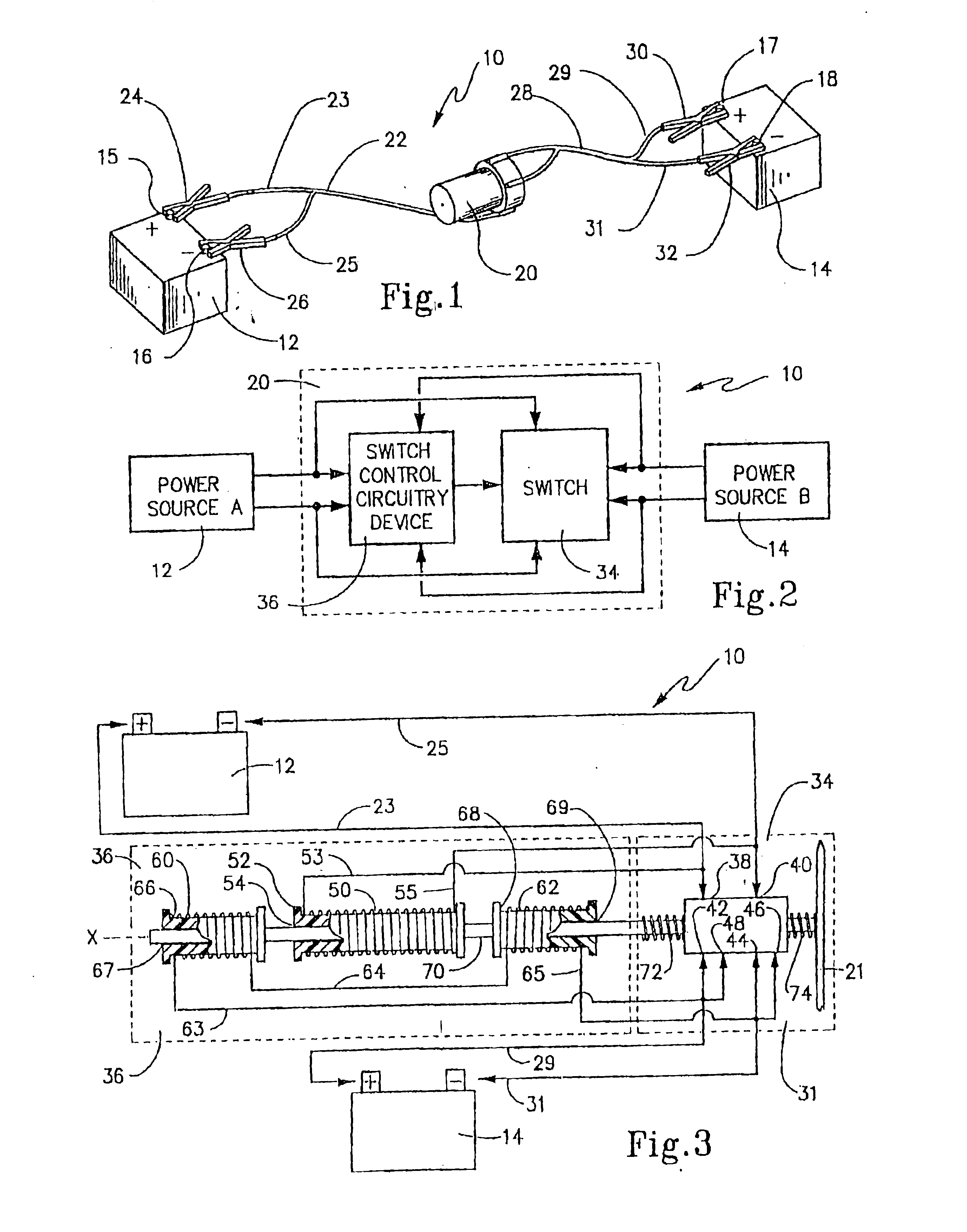
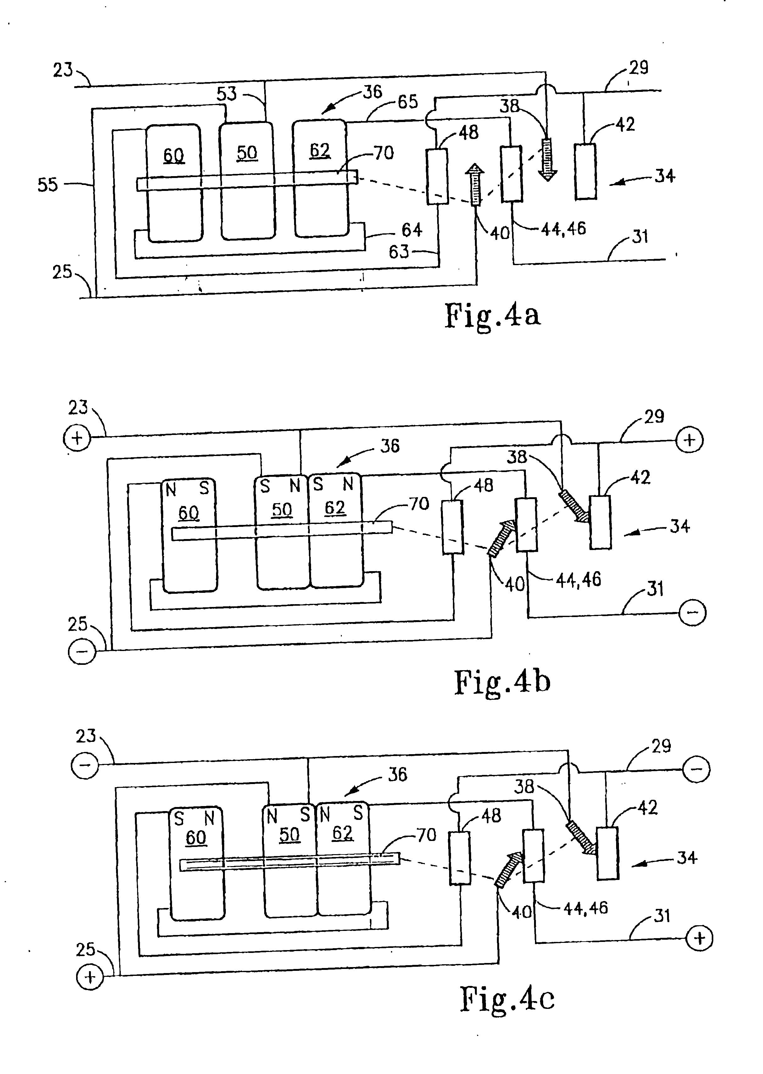
[0016]Accordingly, the present invention is also directed to a method of ensure proper electrical interconnection between a pair of power sources. The method includes these steps of producing a first magnetic field associated with a first one of the power sources, and producing a pair of second magnetic fields associate with a second one of the power sources. A switch is then actuated in response to interaction between the first and second magnetic fields thereby to establish electrical interconnection between like terminals of the power sources. This method accomplishes the step of producing the magnetic fields by interconnecting a first power source to a first current-carrying coil and the step of producing the second magnetic field is accomplished by connecting the second power source to a pair of second current-carrying coils in a manner such that the second magnetic fields are oriented oppositely with respect to one another.

Problems solved by technology

Failure to do so can potentially cause serious damage to either or both vehicles' electrical systems.

Method used


Image

  • Electromechanical switching device
  • Electromechanical switching device
  • Electromechanical switching device

Examples


Embodiment Construction

[0026]The present invention is directed to an electromechanical switching device that automatically provides desired polarity connection between two sources of power. For example, in the vehicle industry, which includes automobiles, buses, etc. and in the watercraft industry, rechargeable batteries are used to start the vehicle's or boat's engine. Sometimes, it is necessary to utilize the battery of one vehicle or craft to boost-start the engine of another. The present invention provides a means for automatically assuring that correct polarity connections between the electrical systems of two vehicles or water crafts are made. Thus, the present invention is described with this application in mind; however, it should be understood that other applications requiring desired polarity interconnection could employ the technique described herein.

[0027]With that in mind, a first exemplary embodiment of the present invention is shown in FIG. 1 wherein electromechanical switching device 10 is...


PUM

PropertyMeasurementUnit
electrical communicationaaaaaaaaaa
magnetic fieldaaaaaaaaaa
magneticaaaaaaaaaa

Abstract

An electromechanical switching device ensures automatic selected polarity interconnection between terminals of two power sources. A double pole double throw (DPDT) switch has three pairs of contacts. A first pair of leads connect to two pairs of contacts in a manner that reverses polarity when switched, while a second pair of leads connect to the other pair of contacts. A switch controller employs a plurality of coils in electrical communication with the two pairs of leads. The coils are arranged and configured so that, when the two pairs of leads are connected to the respective power sources, the coils cause an actuator to move the switch automatically into the correct polarity state regardless of the connections of the leads. The invention is described as a battery jumper cable and to automatically connect like terminals of a pair of batteries. The invention encompasses the method of this device.

Description

RELATED APPLICATION[0001]This application claims the benefit of U.S. Provisional Application No. 60 / 021,435, filed Jul. 9, 1996.FIELD OF INVENTION[0002]The present invention is directed to electromechanical switches for automatically providing a desired polarity connection between two sources of power. Though not by way of limitation, the present invention finds particular application in the automotive field in order to properly interconnect like terminals of a pair of vehicle batteries for recharging.BACKGROUND OF THE INVENTION[0003]Relays and switches are used in a variety of industrial and commercial applications where there is a need to control power. A relay may be either an electromechanical or solid-state device to control other devices connected to an output. Relays are generally associated with controlling the transmission of electric current in a circuit.[0004]Electromechanical relays are used as switches that make or break a circuit by mechanical operation. Here, an elect...

Claims


Application Information

Patent Timeline
Patent Type & Authority Patents(United States)
IPC IPC(8): H02B1/00H02B1/24H01H53/015H01M10/46H02J7/00
CPCH01H53/015H01M10/46H02J7/0034H02J7/0054H02J2001/006H02J1/122H02J7/342Y02E60/10
Inventor SMITH, JERRY R.
Owner SMITH JERRY R
Learn More