
Electrosurgical system

a surgical system and electrode technology, applied in the field of electrosurgical systems, can solve the problems of inability to optimize both the signal supplied by the generator and the choice of electrodes, and the design is relatively complicated, so as to achieve the effect of freeing up additional switching capability and simplifying the switching required

Inactive Publication Date: 2005-08-16
GYRUS MEDICAL LTD
View PDF24 Cites 1317 Cited by
  • Summary
  • Abstract
  • Description
  • Claims
  • Application Information

AI Technical Summary

Benefits of technology

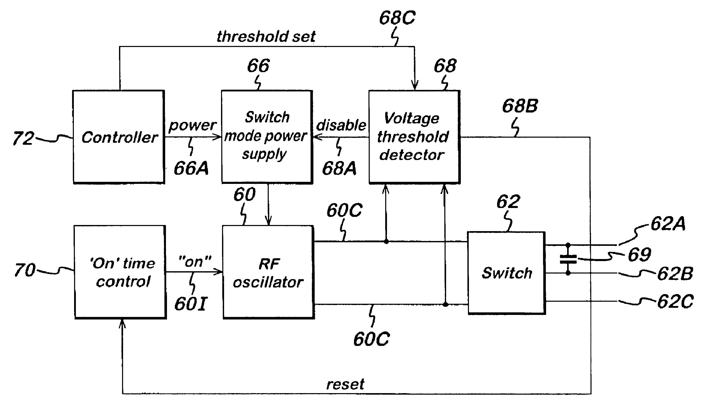
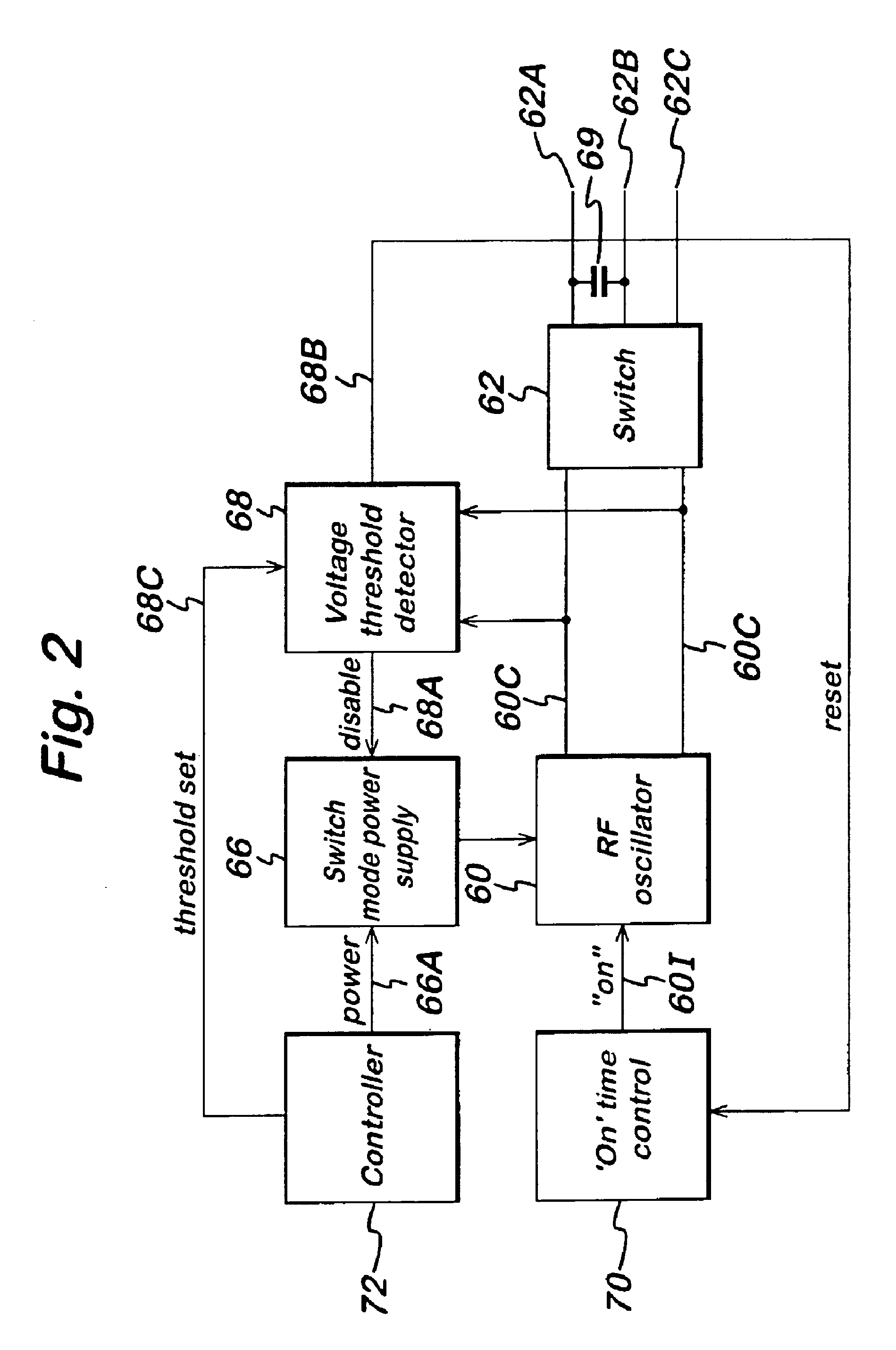
[0008]The capacitor preferably has a value of between 1 and 10 nF. This arrangement can simplify the switching required, and / or free up additional switching capability for use in other circumstances. The switching circuit is preferably located within the generator, although it is conceivable that the switching circuit alternatively be located within the handpiece of the electrosurgical instrument.

Problems solved by technology

The disadvantage of all of these prior art systems is that it is not possible to optimize both the signal supplied by the generator and the choice of electrodes.
U.S. Pat. No. 6,270,497 discloses a device which switches between coagulation and cutting operations, but which is relatively complicated in design.

Method used


Image

  • Electrosurgical system
  • Electrosurgical system
  • Electrosurgical system

Examples


Embodiment Construction

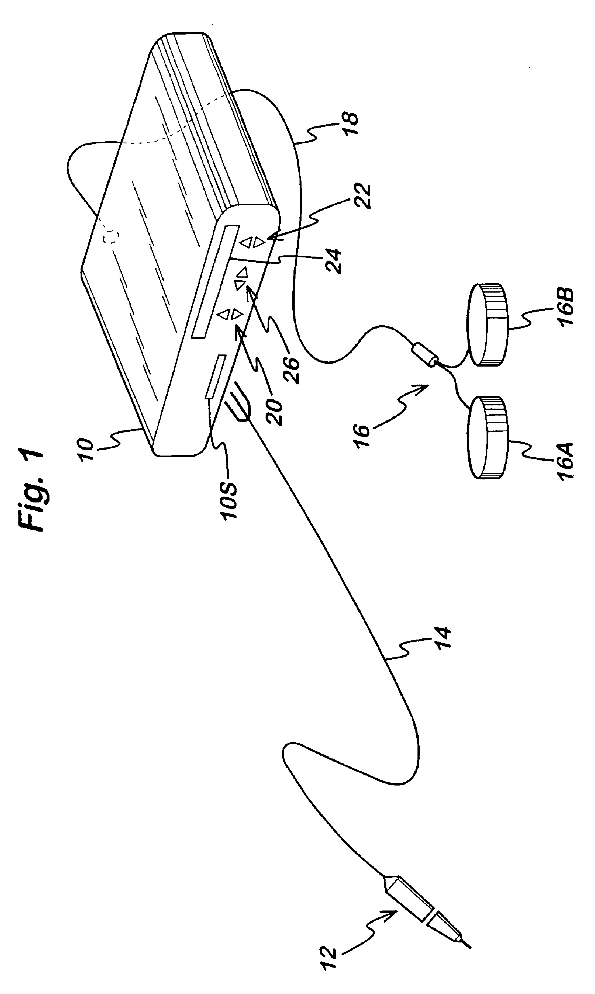
[0038]Referring to FIG. 1, a generator 10 has an output socket 10S providing a radio frequency (RF) output for an instrument 12 via a connection cord 14. Activation of the generator may be performed from the instrument 12 via a connection in cord 14 or by means of a footswitch unit 16, as shown, connected to the rear of the generator by a footswitch connection cord 18. In the illustrated embodiment footswitch unit 16 has two footswitches 16A and 16B for selecting a coagulation mode and a cutting mode of the generator respectively. The generator front panel has push buttons 20 and 22 for respectively setting coagulation and cutting power levels, which are indicated in a display 24. Push buttons 26 are provided as an alternative means for selection between coagulation and cutting modes.

[0039]Referring to FIG. 2, the generator comprises a radio frequency (RF) output stage in the form of a power oscillator 60 having a pair of output lines 60C for coupling via switching circuit 62 to the...


PUM


Abstract

An electrosurgical system includes a generator for generating radio frequency (RF) power, and an electrosurgical instrument including at least three electrodes. The generator comprises an RF output stage having at least a pair of RF output lines, a power supply coupled to the output stage for supplying power to the output stage, and a controller capable of varying the RF power signal supplied to the output lines. The system also includes a selection circuit having at least three output connections each in electrical connection with a respective one of the at least three electrodes. This selection circuit operates to vary the coupling between the RF output stage and the three or more output connections. A switching device operable by the user causes the selection circuit to vary the electrode or electrodes to which RF power is supplied, and also causes the RF power signal supplied to at least one of the at least three output connections to vary depending on the electrode or electrodes to which RF power is supplied. In one arrangement of the selection circuit, one of the electrodes has no direct connection to the output stage of the generator and is connected via a capacitor to another of the electrodes.

Description

CROSS REFERENCE TO RELATED APPLICATION[0001]This is a continuation-in-part of U.S. application Ser. No. 10 / 228,284 filed Aug. 27, 2002, now U.S. Pat. No. 6,878,148, which claims the benefit of U.S. provisional application Ser. No. 60 / 314,650, filed Aug. 27, 2001, the entire contents of both being incorporated herein by reference.FIELD OF THE INVENTION[0002]This invention relates to an electrosurgical system comprising an electrosurgical generator and a handpiece including electrosurgical electrodes. Such systems are commonly used for the cutting and / or coagulation of tissue in surgical intervention, most commonly in “keyhole” or minimally invasive surgery, but also in laparoscopic or “open” surgery.BACKGROUND OF THE INVENTION[0003]It is known to provide electrosurgical generators which provide different radio frequency (RF) power signals for cutting and coagulation, and also to switch between two different instruments, e.g. bipolar and monopolar instruments. In a first type of prior...

Claims


Application Information

Patent Timeline
Patent Type & Authority Patents(United States)
IPC IPC(8): A61B18/12A61B18/14
CPCA61B18/1206A61B18/1442A61B18/12A61B18/1445A61B2017/00212A61B2018/00404A61B2018/00601A61B2018/00607A61B2018/0066A61B2018/00666A61B2018/00678A61B2018/00892A61B2018/124A61B2018/1273
Inventor GOBLE, COLIIN C. O.LATTERELL, SCOTT T.WAHNSCHAFFE, DOUGLAS S.
Owner GYRUS MEDICAL LTD
Learn More