
Microdialysis probe

a microdialysis and probe technology, applied in the field of microdialysis probes, can solve the problems of smallness and the material of the probe, the fragility of the microdialysis probe, and the inability to place the probe, so as to facilitate the placement of the probe

Inactive Publication Date: 2005-08-16
CMAMICRODIALYSIS HLDG
View PDF9 Cites 17 Cited by
  • Summary
  • Abstract
  • Description
  • Claims
  • Application Information

AI Technical Summary

Benefits of technology

[0012]It is thus an object of the invention is to provide a microdialysis probe, the location of which may be monitored and controlled using means such as X-rays or the l

Problems solved by technology

Microdialysis probes are by nature fragile and very small, which requires great care in inserting and withdrawing the probe from the tissue in which it is used.
The use of microdialysis becoming more frequent and common raises other problems such as monitoring and control of the probe during insertion and use.
The monitoring and control of the probe position during insertion / withdrawal and use-has been an obstacle in so far that the smallness and the material of the probe does not make possible the use of common methods for detecting the probe once the insertion has been started.
This becomes more problematic the deeper into the tissue the microdialysis is to take place.

Method used


Image

  • Microdialysis probe
  • Microdialysis probe
  • Microdialysis probe

Examples


first embodiment

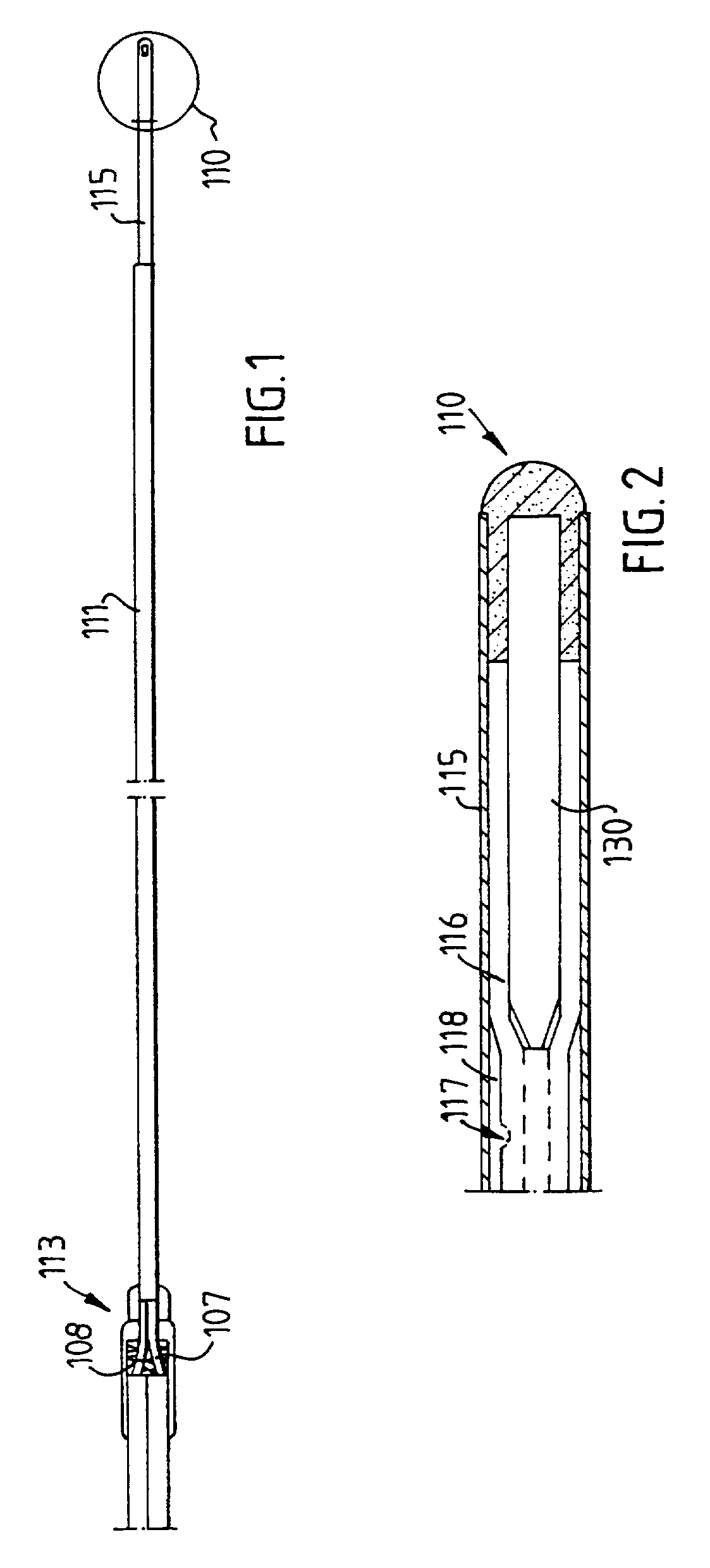
[0020]the microdialysis probe according to the invention is shown in FIG. 1 and FIG. 2. The probe exhibits a distal end piece 110 comprised of glue which holds and seals a plug 130 within the distal part of a membrane 115. This comprises the foremost tip of the probe. The membrane 115 is preferably tubular. A proximal tubular fitting 11 land a proximal end piece 113 comprises the other end of the probe as such. The proximal tubular fitting 111 is permanently fastened to a proximal end piece 113. The proximal end of the membrane 115 is fastened to the proximal tubular fitting 111.

[0021]In the proximal end piece 113 two tubes 107 and 108 constituting the inlet to the probe and the outlet from the probe are connected to the probe, such as to let the perfusion liquid pass through the same. Note in the definitions above the possibility of reversed flow.

[0022]Within the membrane 115, which is in the form of a tube made from semi-permeable material, and also within the proximal tubular fit...

second embodiment

[0025]In a second embodiment the plug 130 may be made such as to make the distal end of the microdialysis probe visible during examination using NMR (Nuclear Magnetic Resonance).

[0026]This plug could e.g. have the form of a hollow amorphous plug filled with air or the like, which would impart characteristics to the plug such that it will be possible to locate the plug using NMR.

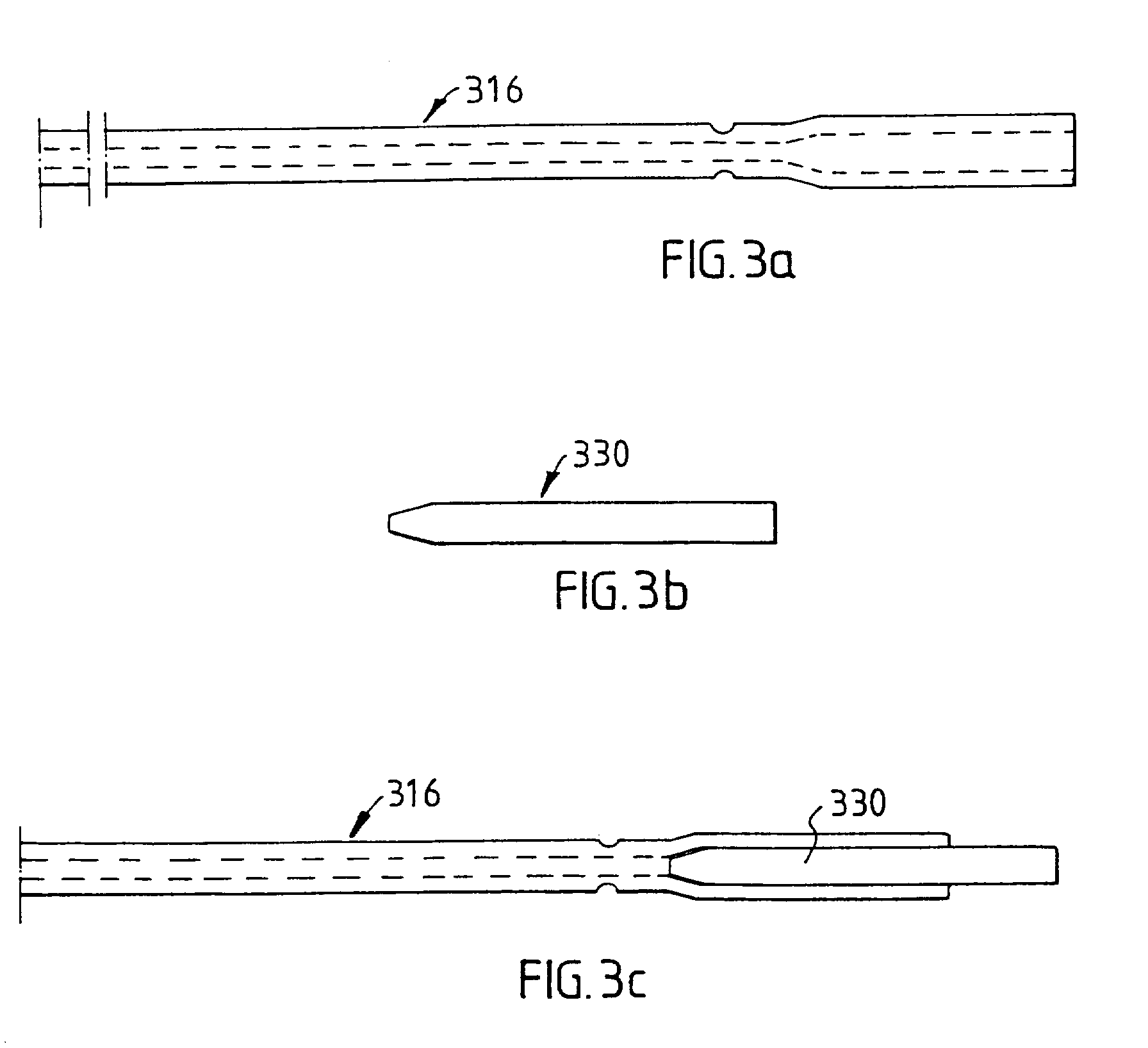
[0027]One way of accomplishing the sealing at the distal end of the first tube 316 is shown in FIG. 3a–c.

[0028]In FIG. 3a) the form of an exemplary first tube 316 according to the invention is shown. The tube has been subjected to corbelling in order to widen the diameter of the same enough to accommodate the sealing plug 330.

[0029]In FIG. 3b) a preferred embodiment of the sealing plug 330 is shown and in FIG. 3c) the first tube 316 with the sealing plug 330 in place is shown.

[0030]A second embodiment of the microdialysis probe according to the invention is shown in FIG. 4. The probe exhibits a distal end pi...


PUM


Abstract

A microdialysis probe includes a dialysis membrane located and supported between a closed distal end of the probe and a proximal end of the same, the membrane essentially surrounding a space for passage of perfusion liquid. The probe has an inlet and outlet for perfusion liquid, where a position indicating object at the distal part of the probe allows non-invasive examination of the location of the distal part of the microdialysis probe.

Description

FIELD OF THE INVENTION[0001]The invention relates to a microdialysis probe. Microdialysis probes of this kind are described in SE-C-434 214, U.S. Pat. No. 5,735,832 and U.S. Pat. No. 5,741,284.[0002]The meaning of specific wordings in this text should be interpreted as follows:[0003]The word probe should be interpreted also as catheter.[0004]The inlet and outlet of the probe as described may in case of a reversed flow be used as outlet and inlet, respectively.[0005]Perfusion liquid is the liquid used in the microdialysis, which is allowed to enter the probe and there take up substances from the surrounding tissue through a membrane.[0006]The perfusion liquid becomes the dialysate after the dialysis.[0007]Non-Invasive investigating examination in this document refers to e.g. X-ray, NMR or the like techniques.BACKGROUND OF THE INVENTION[0008]Microdialysis is a method of examination in which a probe is inserted into tissue in vivo, such that one side of a semi-permeable membrane is in ...

Claims


Application Information

Patent Timeline
IPC IPC(8): A61B5/00A61M1/16A61M1/34A61B5/055A61B5/06G01R33/28A61B6/12A61M1/00A61M1/14A61M1/30
CPCA61B5/145A61B5/14528A61M1/1678A61M1/3427A61M2025/0042A61M25/003A61M1/1682
Inventor JOHANSSON, ROGER
Owner CMAMICRODIALYSIS HLDG
Learn More