
Chair with oscillating seat

Inactive Publication Date: 2005-08-16
PRO CORD SPA
View PDF13 Cites 35 Cited by
  • Summary
  • Abstract
  • Description
  • Claims
  • Application Information

AI Technical Summary

Benefits of technology

[0003]The object of the present invention is to provide an enhanced chair which allows to overcome the aforesaid drawbacks.

Problems solved by technology

One of the main drawbacks of traditional solutions is that said adjusting device is usually located underneath the seat, in a position that is difficult to reach by the user.
Moreover, known adjusting devices require a large actuating force, which makes the adjustment operation difficult.

Method used


Image

  • Chair with oscillating seat
  • Chair with oscillating seat
  • Chair with oscillating seat

Examples


Embodiment Construction

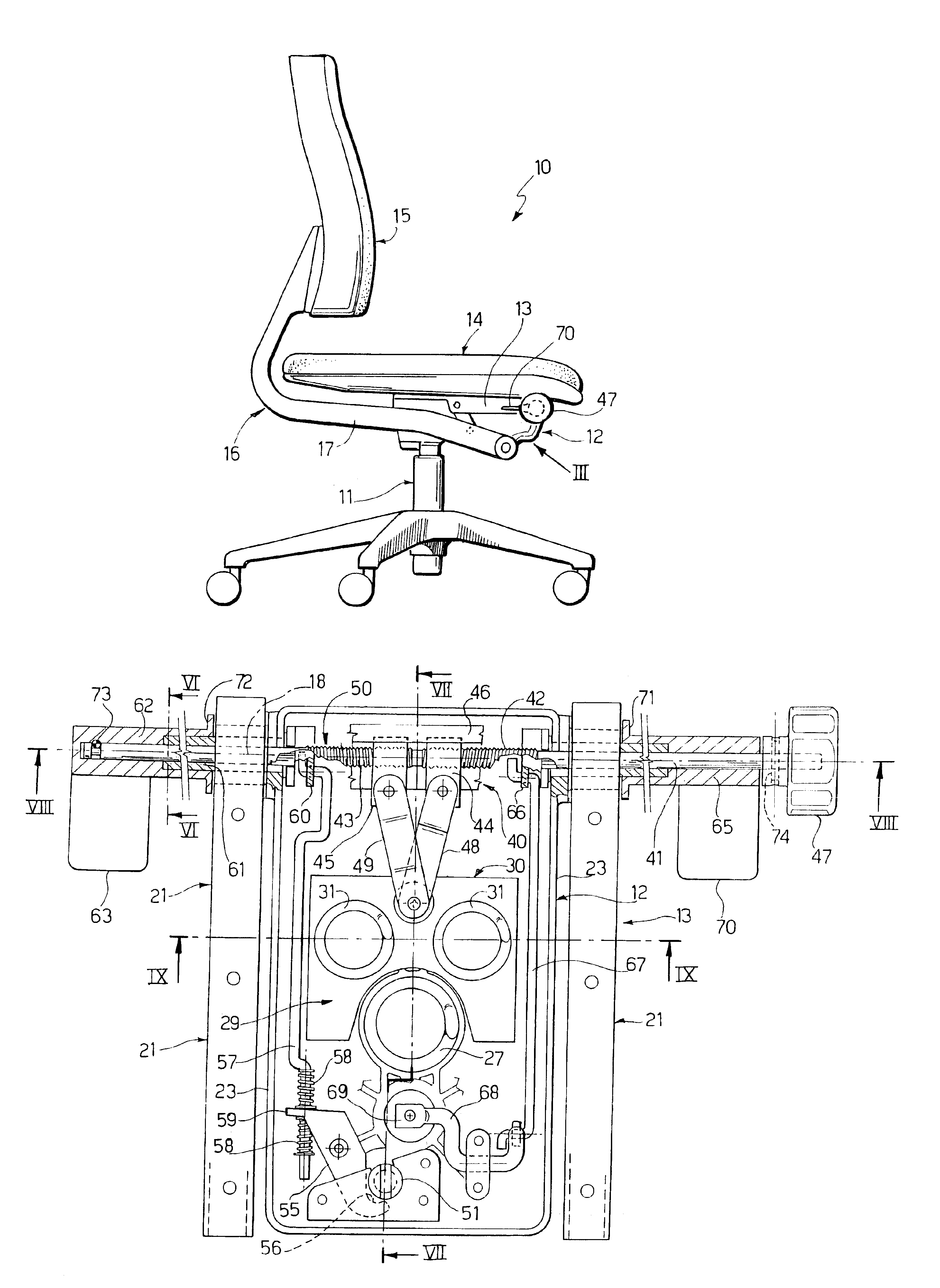
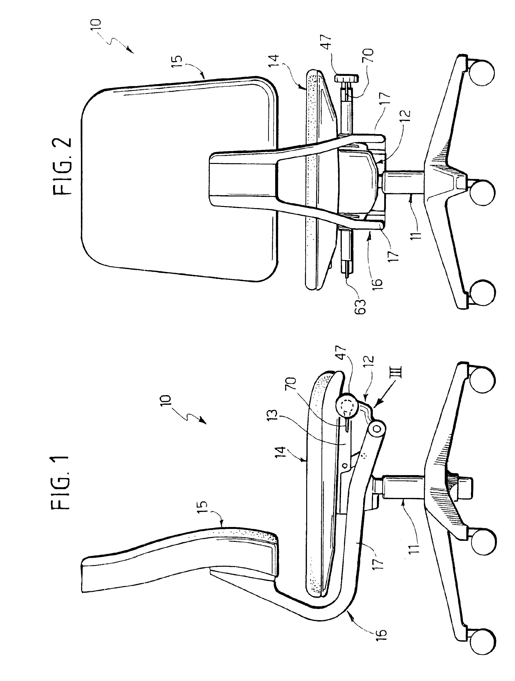
[0016]With reference to FIGS. 1 and 2, an office chair according to the present invention is designated as 10. The chair 10 comprises a central column 11 with adjustable height which bears at its upper end a base structure 12. The base structure 12 bears a seat support structure 13 whereon is fastened a seat 14. The chair 10 comprises a backrest 15 borne by a backrest support structure 16. The backrest support structure 16 comprises two arms 17 which extend laterally and from opposite sides relative to the base structure 12.

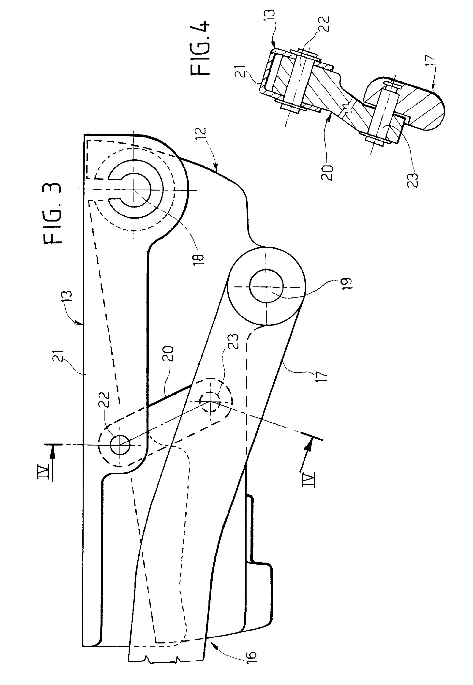
[0017]With reference to FIG. 3, the seat support structure 13 is articulated to the base structure 12 around a first transverse axis 18 which extends orthogonally to the plane of representation of FIG. 3. The axis 18 is positioned near the front end of the base structure 12.

[0018]The arms 17 of the backrest support structure are articulated to the base structure around a second transverse axis 19, parallel to the first transverse axis 18. The second transverse ax...


PUM


Abstract

A chair, in particular an office chair, comprising: a base structure, a seat support structure, articulated to the base structure around a transverse axis, an adjustable elastic device to apply an elastic force between the base structure and the seat support structure, a manually operated adjustment device for varying the distance between said adjustable elastic device and said transverse axis.

Description

BACKGROUND OF THE INVENTION[0001]The present invention relates to a chair, in particular an office chair, comprising a base structure, a seat support structure articulated to the base around a transverse axis and an adjustable elastic device to apply an elastic force between a base structure and the seat support structure.[0002]Traditional office chairs are usually provided with a compressed spring positioned between the base structure and the seat support structure. Normally, an adjusting device is provided which allows the user to adjust the compression pre-load of the spring to vary the elastic reaction force according to his / her needs. One of the main drawbacks of traditional solutions is that said adjusting device is usually located underneath the seat, in a position that is difficult to reach by the user. Moreover, known adjusting devices require a large actuating force, which makes the adjustment operation difficult. The actuating force the user must manually apply to the adj...

Claims


Application Information

Patent Timeline
IPC IPC(8): A47C7/35A47C1/031A47C7/14A47C1/032A47C7/02
CPCA47C1/03255A47C1/03266A47C1/03272A47C7/14A47C7/345
Inventor PIRETTI, GIANCARLO
Owner PRO CORD SPA
Learn More