
Adjustable keyboard support

a keyboard and adjustable technology, applied in the field of adjustable supports, can solve the problems of difficult to locate the keyboard thereon, many users do not prefer to locate the keyboard on the desktop, and many systems are structurally complex and typically require rather awkward adjustments, so as to reduce frictional engagement

Inactive Publication Date: 2005-08-16
STEELCASE INC
View PDF21 Cites 21 Cited by
  • Summary
  • Abstract
  • Description
  • Claims
  • Application Information

AI Technical Summary

Benefits of technology

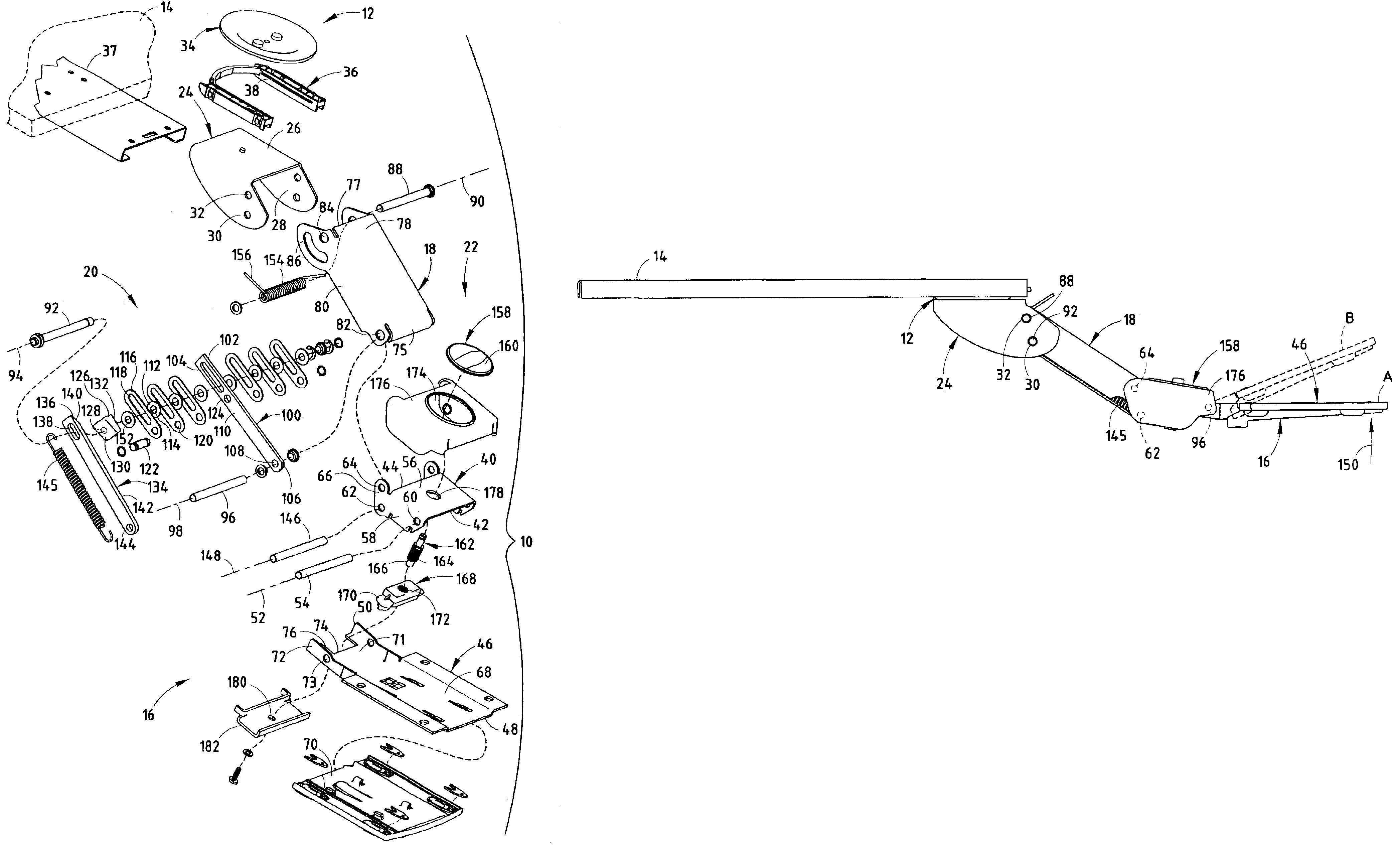
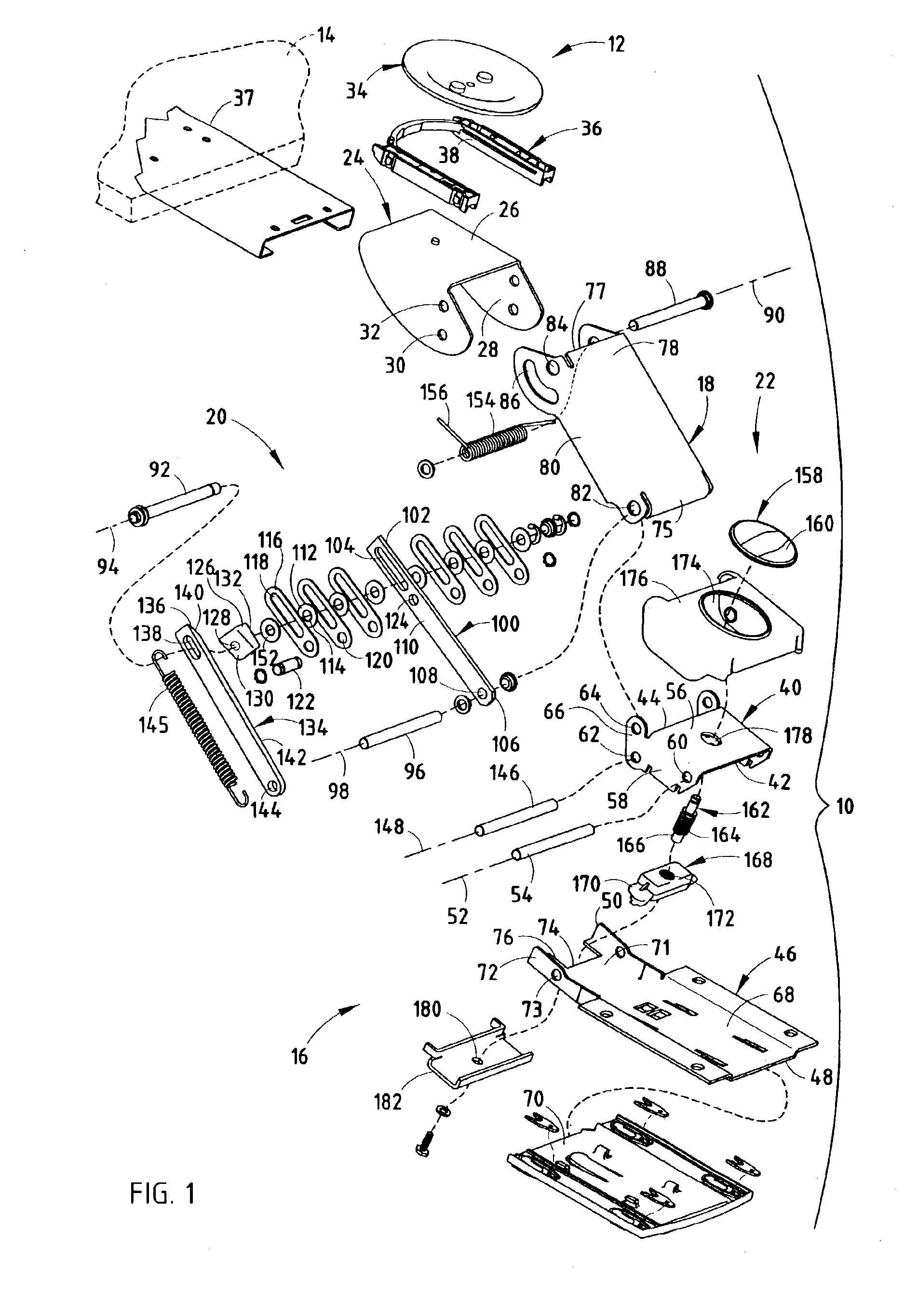
[0004]One aspect of the present invention is to provide an adjustable keyboard support mechanism that includes a mounting bracket adapted for attachment to a support surface, a platform having a forward portion and a rearward portion thereof disposed generally opposite the forward portion, and a support arm having a first end thereof pivotally coupled with the mounting bracket at a first point and slidably coupled with the mounting bracket at a second point, and a second end pivotally coupled with the platform at a third point. The adjustment keyboard support mechanism also includes a locking mechanism including a center arm having a first end slidably coupled to the mounting bracket at the second point, and pivotally coupled with the platform at the third point, such that an upwardly directed force exerted on the front side of the platform allows the center arm to slide with respect to the second point. The locking mechanism also includes at least two planar frictional members sandwiching and frictionally engaging the center arm, such that the sliding movement of the center arm with respect to the second point is restricted, and a wedge member having an angled surface, and an abutment surface opposite the angle surface of the wedge member and adapted to abut one of the frictional members. The locking member further includes a wedge arm having a first end pivotally coupled to the platform at a fourth point, and a second end slidably coupled to the mounting bracket at the second point such that the upwardly-directed force exerted on the front edge of the platform causes the wedge arm to slide with respect to the second point. The second end of the wedge arm includes an angled surface adapted to abut the angled surface of the wedge arm such that sliding of the wedge arm due to the upwardly-directed force exerted on the platform reduces a force exerted on the wedge member by the wedge arm and reduces the frictional engagement between the frictional member and the center arm, thereby allowing the center arm to slide with respect to the second point and the height of the platform to be adjusted relative to the support surface.
[0007]The present inventive adjustable keyboard support mechanism provides an uncomplicated design, can be easily and quickly adjusted by the end user is efficient in its use, economical to manufacture, capable of a long operating life, and is particularly well adapted for the proposed use.

Problems solved by technology

Often, the personal computer occupies much of the desk or worksurface making it difficult to locate the keyboard thereon.
Furthermore, many users do not prefer to locate the keyboard on the desktop because it is uncomfortable to address the keyboard over the course of the workday.
Many of these systems are structurally complex and typically require rather awkward adjustments through manipulations of a number of knobs, levers, and / or handles.
Moreover, many of the adjustable keyboard supports available today utilize an adjustment system which is counter-intuitive, insofar as the end user must learn a detailed sequence of steps, knobs, controls, locks, etc., before the device can be used effectively instead of simply moving the keyboard directly to the desired position.

Method used


Image

  • Adjustable keyboard support
  • Adjustable keyboard support
  • Adjustable keyboard support

Examples


Embodiment Construction

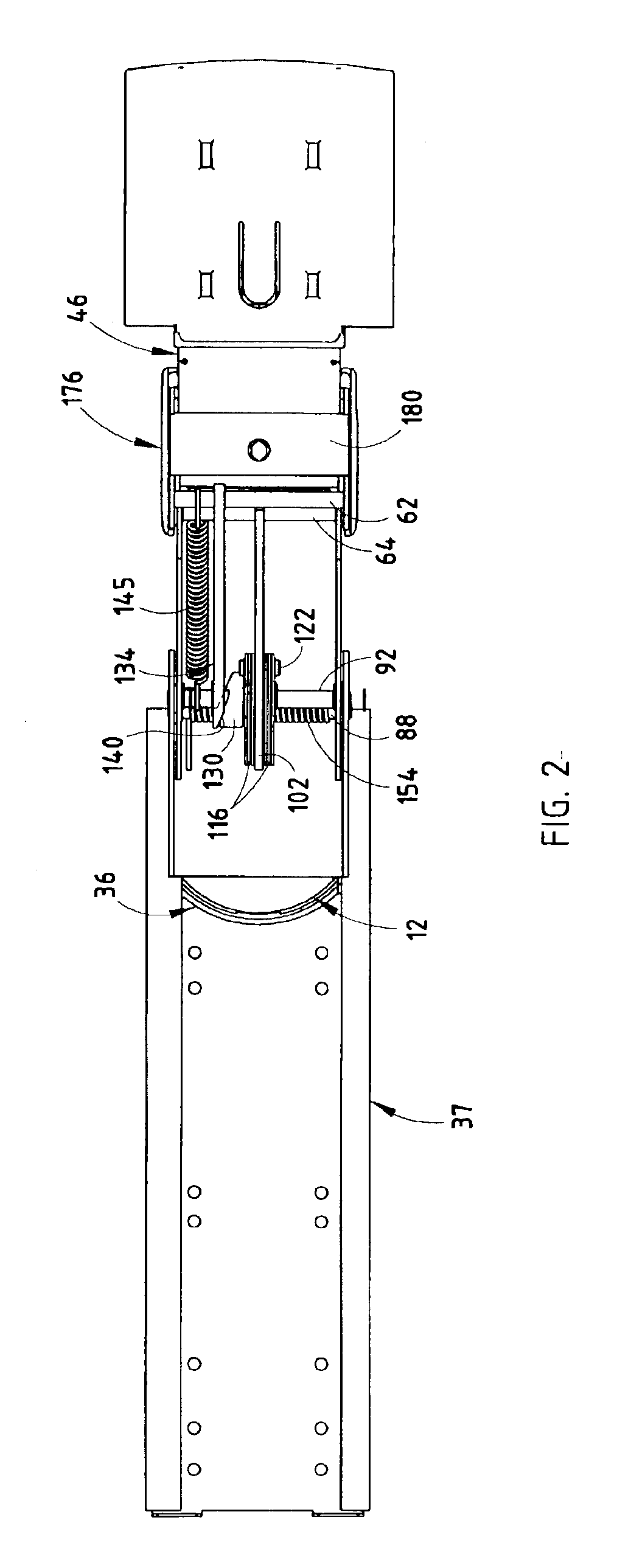
[0012]For purposes of description herein, the terms “upper,”“lower,”“right,”“left,”“rear,”“front,”“vertical,”“horizontal,” and derivatives thereof shall relate to the invention as oriented in FIGS. 1 and 2. However, it is to be understood that the invention may assume various alternative orientations and step sequences, except where expressly specified to the contrary. It is also to be understood that the specific devices and processes illustrated in the attached drawings, and described in the following specification are exemplary embodiments of the inventive concepts defined in the appended claims. Hence, specific dimensions and other physical characteristics relating to the embodiments disclosed herein are not to be considered as limiting, unless the claims expressly state otherwise.

[0013]The reference numeral 10 (FIG. 1) generally designates a keyboard support mechanism embodying the present invention. In the illustrated example, the keyboard support mechanism 10 includes numerou...


PUM


Abstract

An adjustable keyboard support mechanism includes a mounting bracket for attachment to a support surface, a platform for supporting a keyboard thereon, a support arm operably connected to the mounting bracket and the platform, and a locking mechanism for restricting height adjustment of the platform with respect to the support surface. The locking mechanism includes a center arm pivotable with respect to the platform and slidable with respect to the mounting bracket, a plurality of frictional members sandwiching and frictionally engaging the center arm, thereby restricting the sliding movement of the center arm with respect to the mounting bracket, and a wedge assembly actuable by pivoting movement of the platform and engageable with the frictional members to both restrict and allow height adjustment of the platform relative to the support surface. The adjustable keyboard support further includes a tilt adjustment mechanism having an actuator member defining a length and operably coupled to a first portion of the platform and linking member operably coupled to a second section of the platform and adjustable along the length of the actuator such that an adjustment of the linking member along the length of the actuator member causes the second section of the platform to pivot with respect to the first section, thereby adjusting a tilt of the second section of the platform relative to the support surface.

Description

BACKGROUND OF THE INVENTION[0001]This invention relates generally to adjustable supports, and in particular to an articulating platform or support for a data input device, such as a computer keyboard, mouse, or the like.[0002]Personal computers are becoming more and more common in many industries and office environments, and such systems typically employ a keyboard, key pad, mouse, and / or other date input devices, such as a digitizing pad. Often, the personal computer occupies much of the desk or worksurface making it difficult to locate the keyboard thereon. Furthermore, many users do not prefer to locate the keyboard on the desktop because it is uncomfortable to address the keyboard over the course of the workday.[0003]A number of devices have been developed to offer greater flexibility in supporting the keyboard, mouse, or other device at a comfortable position relative to the user. Many of these systems are structurally complex and typically require rather awkward adjustments th...

Claims


Application Information

Patent Timeline
Patent Type & Authority Patents(United States)
IPC IPC(8): A47B21/03A47B21/00
CPCA47B21/0314Y10S248/918
Inventor WHITAKER, RUSSELLWILLIAMSON, SCOTT A.BARBER, PETER M.LECLAIR, JAMES L.ROODVOETS, PHILIP
Owner STEELCASE INC
Learn More