Fluid coupling

Inactive Publication Date: 2005-08-16
ISUZU MOTORS LTD
View PDF1 Cites 6 Cited by
  • Summary
  • Abstract
  • Description
  • Claims
  • Application Information

AI Technical Summary

Benefits of technology

[0016]the centrifugal operation means brings the second baffle plate relative to the first baffle plate to such a position that the amount of overlapping of the first openings and the second openings decreases when the rotational speed of the first baffle plate is low, and turns the second baffle plate relative to the first baffle plate so as to increase the amount of overlapping of the first openings and the second openings when the rotational speed of the first baffle plate increases.

Problems solved by technology

When the drag torque is large, the engine loses stability to a conspicuous degree during the idling operation and, besides, this unstable rotation becomes a cause of generating abnormal vibration in the drive system.
Besides, a large drag torque is detrimental to the fuel efficiency during the idling operation.
The fluid couplings shown in FIGS. 12 and 13 employ a fixed baffle plate and have effect to change the characteristics of coefficient (τ) of input capacity for the speed ratio (e) of the pump and the turbine, but is not capable of changing the τ-characteristics for the input rotational speed.
In this case, however, the transmission torque, too, becomes small at the time of start, and the vehicle cannot start moving unless the engine rotational speed is considerably increased thereby causing the fuel efficiency to be deteriorated.
On the other hand, if τ (e=0) is increased to increase the transmission torque at the time of start, the drag torque at the time of idling is also increased thereby causing the fuel efficiency to be deteriorated at the time of idling, though a large start torque is obtained.
As described above, in the fluid coupling using the fixed baffle plate there exists a trade-off relationship between the drag torque during the idling and the fuel efficiency, which cannot be solved.
According to the fluid coupling disclosed in the above JP-A 2001-50309, however, it is not possible to change the effective baffle area of the baffle plate in response to the rotational speed.

Method used


Image

  • Fluid coupling
  • Fluid coupling
  • Fluid coupling

Examples


first embodiment

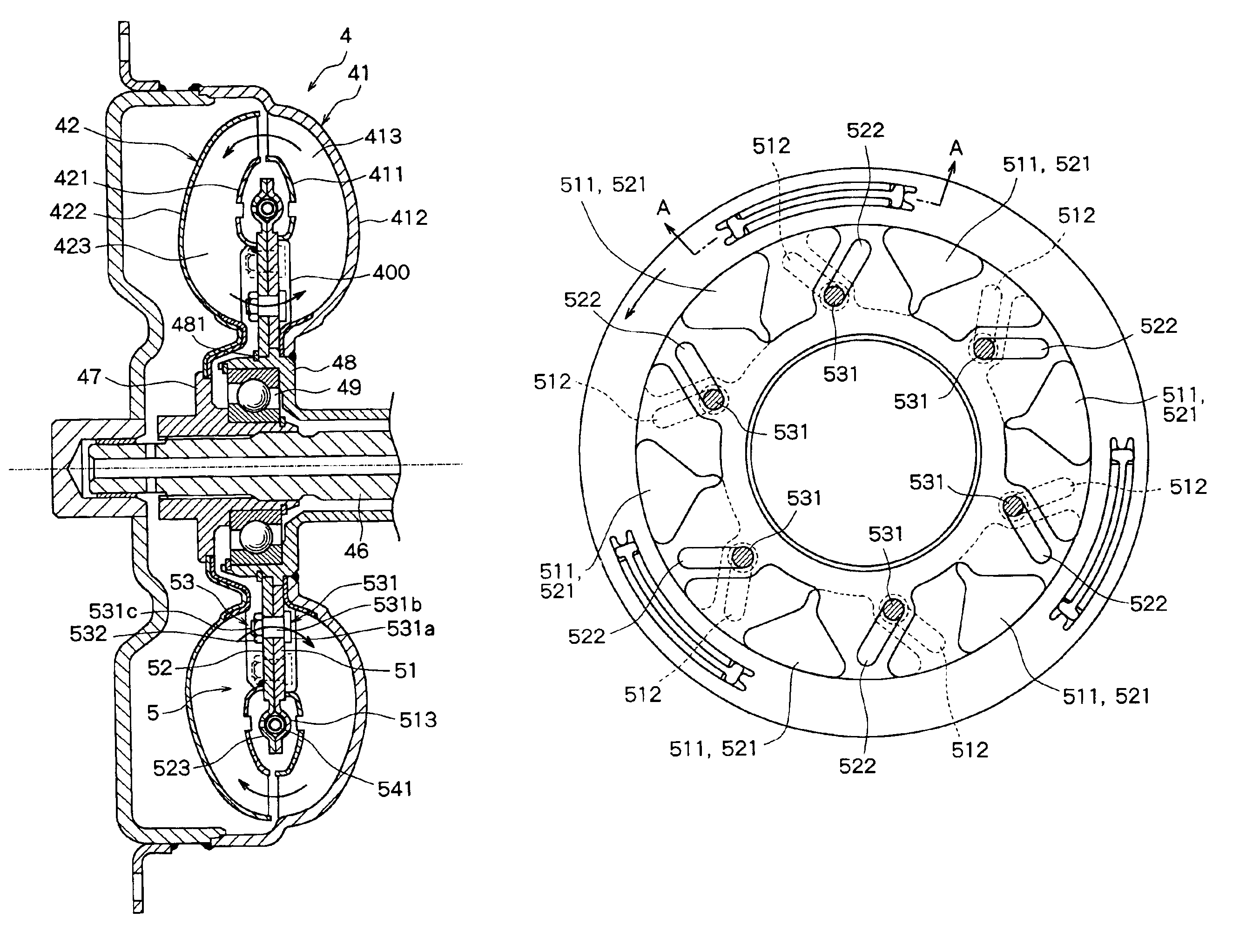
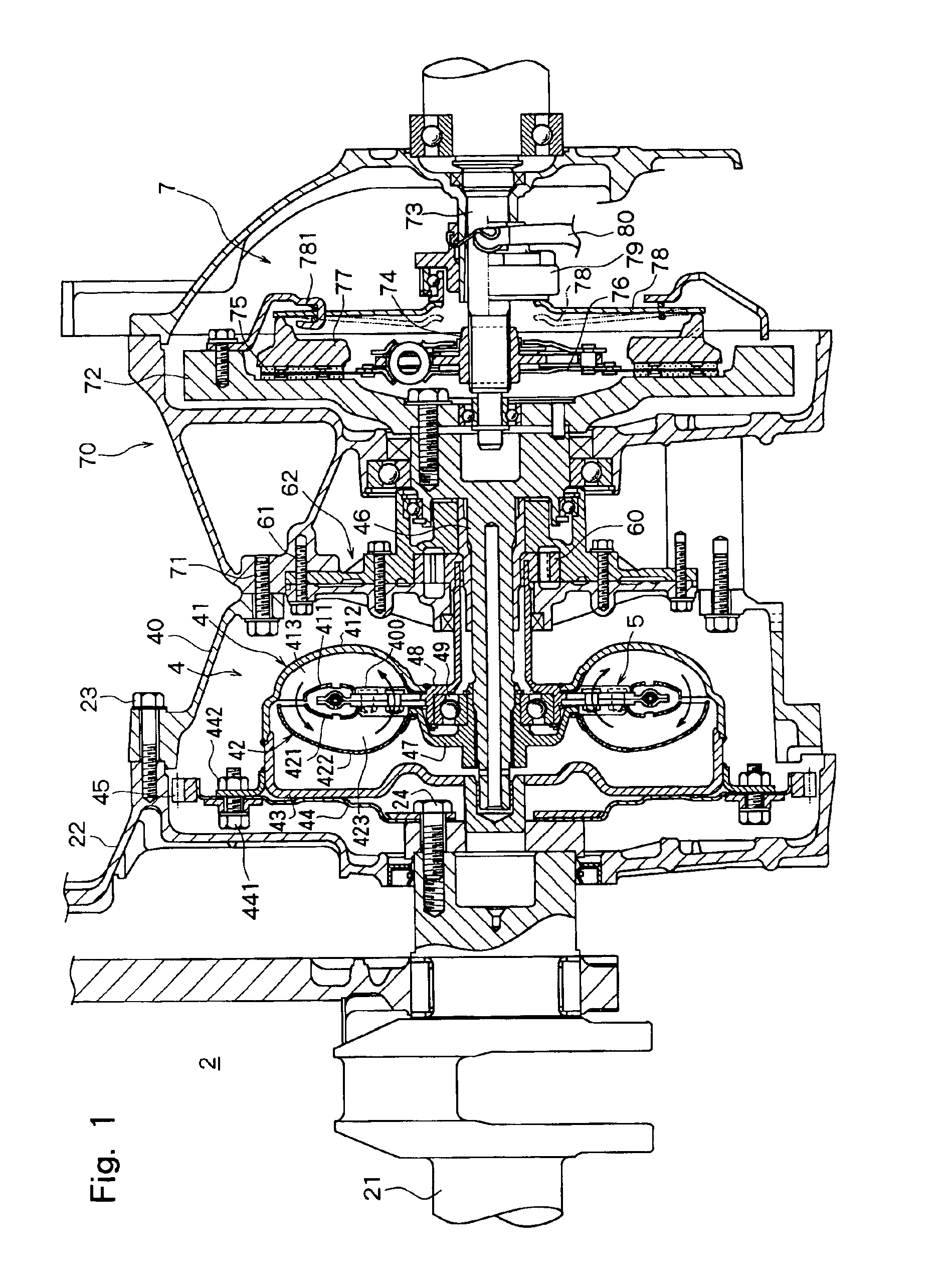
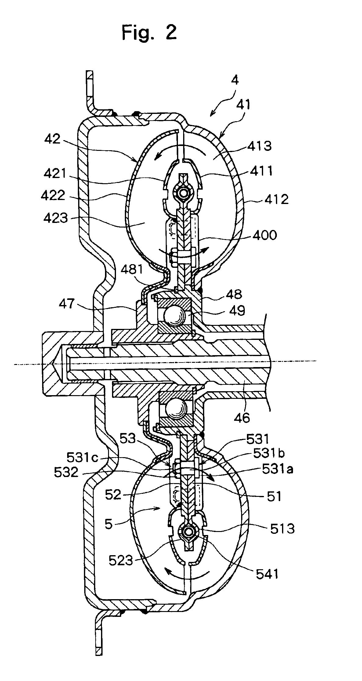
[0042]Next, the above baffle mechanism 5 according a first embodiment will be described with reference to FIGS. 2 to 7.

[0043]The baffle mechanism 5 according to the first embodiment has a first annular baffle plate 51 and a second annular baffle plate 52 which are arranged between the pump shell 412 and the turbine 422. Referring to FIG. 3, the first baffle plate 51 has a plurality (six in the illustrated embodiment) of first openings 511 formed in the circumferential direction and a plurality (six in the illustrated embodiment) of first elongated holes 512 which are formed, between the first openings 511, at a tilt of a predetermined angle with respect to the straight lines in the radial direction passing through the center. The thus formed first baffle plate 51 has its inner periphery fitted onto the pump hub 48 and has its outer periphery arranged in space formed by the core ring 411 of the pump shell 412 and the core ring 421 of the turbine shell 422. The first baffle plate 51 i...

second embodiment

[0051]The baffle mechanism 5a uses helical extension springs 541a as resilient urging means 54a for turning the second baffle plate 52 in a predetermined direction relative to the first baffle plate 51. To arrange the helical extension springs 541a, three notches 514 and 524 are formed in the outer peripheral portions of the first baffle plate 51 and the second baffle plate 52. The helical extension springs 541a disposed in the respective three notches 514 and 524 are hooked, at the ends on one side, to the first baffle plate 51 and are hooked, at the ends on the other side, to the second baffle plate 52. Therefore, the second baffle plate 52 is urged by the spring forces of the helical extension springs 541a to turn in a direction indicated by an arrow in FIG. 8. As a result, the inner ends of the first elongated holes 512 formed in the first baffle plate 51 are located at positions to be overlapped with inner ends of the second elongated holes 522 formed in the second baffle plat...


PUM


Abstract

A fluid coupling comprising a pump having a pump shell and a plurality of impellers arranged in the pump shell, a turbine having a turbine shell arranged to be opposed to the pump and a plurality of runners arranged in the turbine shell, and a baffle mechanism arranged in a fluid circulation passage formed by the pump shell and the turbine shell, wherein the baffle mechanism comprises a first baffle plate having a plurality of first openings, a second baffle plate that has a plurality of second openings and is disposed in such a manner as to overlap with the first baffle plate and as to be allowed to rotate relative thereto, and a centrifugal operation means for turning the second baffle plate relative to the first baffle plate in response to the rotational speed of the first baffle plate.

Description

FIELD OF THE INVENTION[0001]The present invention relates to an improvement on a fluid coupling for transmitting a rotational torque of a prime mover.DESCRIPTION OF THE RELATED ART[0002]A fluid coupling has heretofore been used as a power transmission coupling for ships, industrial machinery and automobiles. The fluid coupling comprises a pump having an annular pump shell and a plurality of impellers radially arranged in the pump shell, and a turbine that has an annular turbine shell and a plurality of runners radially arranged in the turbine shell and is disposed opposite to the pump, and the pump and the turbine are filled with an operation fluid. In the thus constituted fluid coupling, the pump is coupled to a crank shaft (an input shaft as the fluid coupling) of a prime mover that may be, for example, a diesel engine, and the turbine is mounted on the output shaft arranged on same axis line as the input shaft.[0003]Further, there is also used a fluid coupling in which the pump s...

Claims


Application Information

Patent Timeline
IPC IPC(8): F16D33/18F16D33/00F16D33/02F16H41/26F16H41/04
CPCF16D33/02F16D33/18
Inventor YAMAMOTO, YASUSHIIWAO, NOBUYUKI
Owner ISUZU MOTORS LTD
Why Eureka
Try Eureka