
Intelligent drag of assembly components

a technology of assembly components and intelligent drag, applied in the direction of static indicating devices, instruments, configuration cad, etc., can solve the problems of laborious process, placing/positioning graphical components in accordance with constraints, etc., and achieve the effect of quick mate of components

Inactive Publication Date: 2005-08-09
AUTODESK INC
View PDF14 Cites 53 Cited by
  • Summary
  • Abstract
  • Description
  • Claims
  • Application Information

AI Technical Summary

Benefits of technology

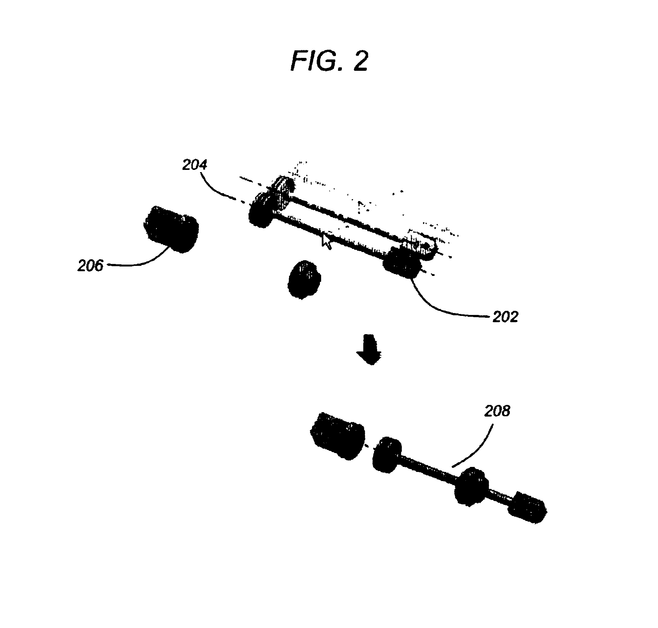
[0013]This “click-n-drag” style assembly mating offers users more control over how constraints are applied and can be activated or de-activated by simply holding down a key (e.g., the ALT or CTRL key) when selecting the part to be positioned. Accordingly, a user is provided with a way to quickly mate components without ever bothering to actually enter a constraint command.

Problems solved by technology

However, placing / positioning a graphical component in accordance with a constraint (as desired) is often a laborious process that requires significant user interaction through a graphical user interface.

Method used


Image

  • Intelligent drag of assembly components
  • Intelligent drag of assembly components
  • Intelligent drag of assembly components

Examples


Embodiment Construction

[0020]In the following description, reference is made to the accompanying drawings which form a part hereof, and which is shown, by way of illustration, several embodiments of the present invention. It is understood that other embodiments may be utilized and structural changes may be made without departing from the scope of the present invention.

Hardware Environment

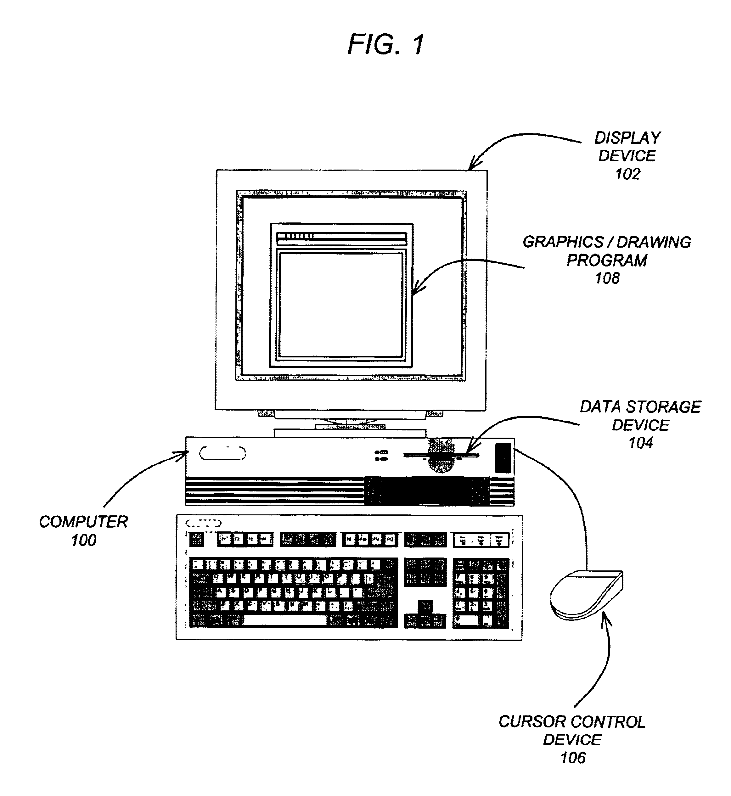
[0021]FIG. 1 is an exemplary hardware and software environment used to implement one or more embodiments of the invention. Embodiments of the invention are typically implemented using a computer 100, which generally includes, inter alia, a display device 102, data storage devices 104, cursor control devices 106, and other devices. Those skilled in the art will recognize that any combination of the above components, or any number of different components, peripherals, and other devices, may be used with the computer 100.

[0022]One or more embodiments of the invention are implemented by a computer-implemented graphics program...


PUM


Abstract

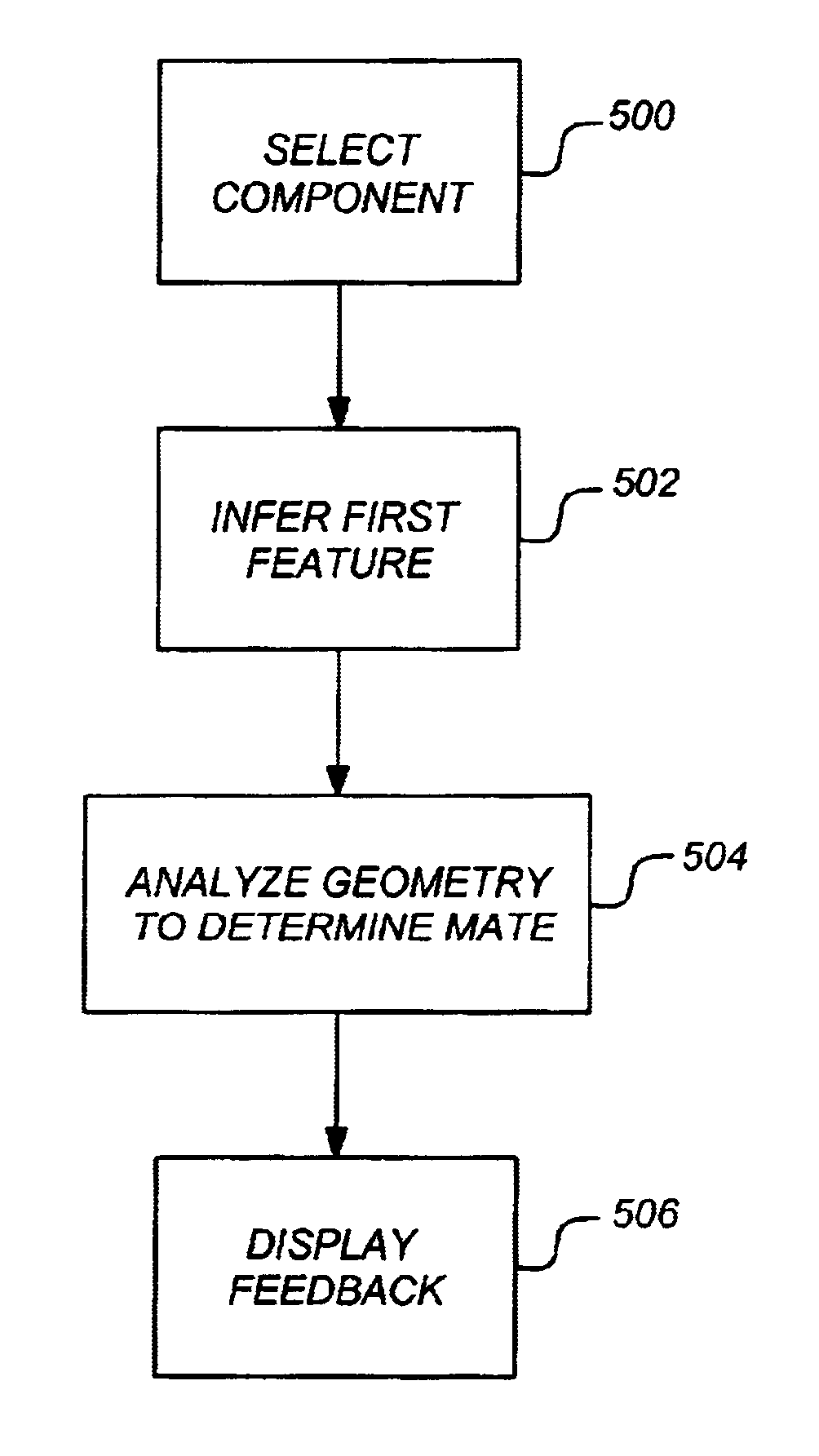
One or more embodiments of the invention provide a method, apparatus, and article of manufacture for positioning a graphical component in a computer-implemented drawing program. A selection of a graphical component displayed on a display device is received. Thereafter, a first feature of the graphical component is inferred. The display of the graphical component is moved (e.g., by a user using a cursor control device). Underlying geometry is then analyzed to determine one or more second features of the underlying geometry that can mate with the first feature. Feedback is then displayed that indicates placement potential for the graphical component based on the first feature mating with one of the second features.

Description

CROSS-REFERENCE TO RELATED APPLICATIONS[0001]This application is related to the following co-pending and commonly-assigned patent application, which application is incorporated by reference herein:[0002]U.S. patent application Ser. No. 09 / 966,656, entitled “INTELLIGENT CONSTRAINT DEFINITIONS FOR ASSEMBLY PART MATING”, filed on Sep. 28, 2001 by Scott T. Kohls, et. al.BACKGROUND OF THE INVENTION[0003]1. Field of the Invention[0004]The present invention relates generally to computer-implemented drawing programs, and in particular, to a method, apparatus, and article of manufacture for dragging and intelligently placing assembly components in a drawing.[0005]2. Description of the Related Art[0006]Computer-implemented drawing programs (e.g., a solid modeling or computer aided design [CAD] program) are often used to create, view, and modify solid models, assemblies, diagrams, flow charts, blue-prints, etc. (collectively referred to as drawings) in both two dimensions (2D) and three dimens...

Claims


Application Information

Patent Timeline
Patent Type & Authority Patents(United States)
IPC IPC(8): G06F3/00G09G5/00G06T19/20
CPCG06T17/10G06T19/20G06T2219/2008G06T2200/24G06T2219/2021G06F30/12G06F30/17G06F2111/20G06F2111/04
Inventor KOHLS, SCOTT T.SMITH, GARY R.
Owner AUTODESK INC
Learn More