Continuously variable transmission, endless flexible belt for torque transmission and adjustable pulley

Inactive Publication Date: 2005-08-09
VAN DOORNES TRANSMISSIE BV
View PDF6 Cites 13 Cited by
  • Summary
  • Abstract
  • Description
  • Claims
  • Application Information

AI Technical Summary

Benefits of technology

[0006]An alternative advantage of the CVT according to the invention is that the mutual orientation of the sheave faces of a pulley may be allowed to change slightly under the influence of the clamping force, without the pulley angle becoming disadvantageously larger than the belt angle. So, even when coping with a relatively high level of the clamping force that can occur in automotive applications, the pulleys of a CVT according to the invention need not necessarily be as rigidly designed as the known pulleys for automotive application. According to the invention, strengthening features of the pulley sheaves, such as radially oriented ribs, may therefore be reduced in size, or even omitted, yielding lighter and more cost effective pulley / designs.
[0010]In a further development of the invention the pulley angle of a pulley decreases in a radially outward direction along at least a substantial part of the radial dimension of the pulley sheaves. With this measure it is achieved that the axial deformation of the pulley sheaves can be compensated for, at least in a substantial part of a range of radial positions of the interaction. Thereby, it is advantageously achieved that the contact pressure between the pulley sheaves and the flexible belt is distributed more evenly. A relatively simple and cost effective manner for realising the measure according to the invention is found in providing at least one sheave face with a concave curvature as seen in tangential cross section of the sheave. For optimum results in typical automotive application of the CVT, the radius of the concave curvature has a value in a range from 5 to 100 meter. Such range being based on the preferred range of values for the difference between the pulley angle and the belt angle.
[0013]In an alternative embodiment of the development of the invention, the pulley angle decreases in the radially outward direction, such that when during operation a clamping force is at a level that is the most frequently applied, the belt angle substantially corresponds to the pulley angle, at least at the instantaneous radial position of the interaction. In this manner it is achieved that during operation and at the radial position of the interaction the difference between the belt angle and the pulley angle is on average minimised.
[0014]In yet another alternative embodiment of the development of the invention, the pulley angle decreases in the radially outward direction, such that when during operation a clamping force is at an average level, the belt angle substantially corresponds to the pulley angle, at least at the instantaneous radial position of the interaction. In this manner it is achieved that during operation and at the radial position of the interaction the maximum difference between the belt angle and the pulley angle is minimised.

Problems solved by technology

Such deflection probably causes the flexible belt to be borne unstable, but is considered to be at least responsible for additional wear of the flexible belt.
Moreover, the measure can prevent that the contact pressure between sheaves and a lateral side face decreases in radially outward direction, which would cause an unstable configuration and could lead to deformation of the flexible belt.
In the latter case, a decreasing contact pressure in radially outward direction constitutes an unstable configuration in which the transverse elements may tilt between the sheaves with respect to the radial direction, thereby mutually causing local wear on or in the vicinity of the projection and recess.
A further disadvantage of such tilting is that is accompanied by slip between the sheaves and the transverse elements, whereby the efficiency of the CVT is reduced as a consequence.

Method used


Image

  • Continuously variable transmission, endless flexible belt for torque transmission and adjustable pulley
  • Continuously variable transmission, endless flexible belt for torque transmission and adjustable pulley
  • Continuously variable transmission, endless flexible belt for torque transmission and adjustable pulley

Examples


Embodiment Construction

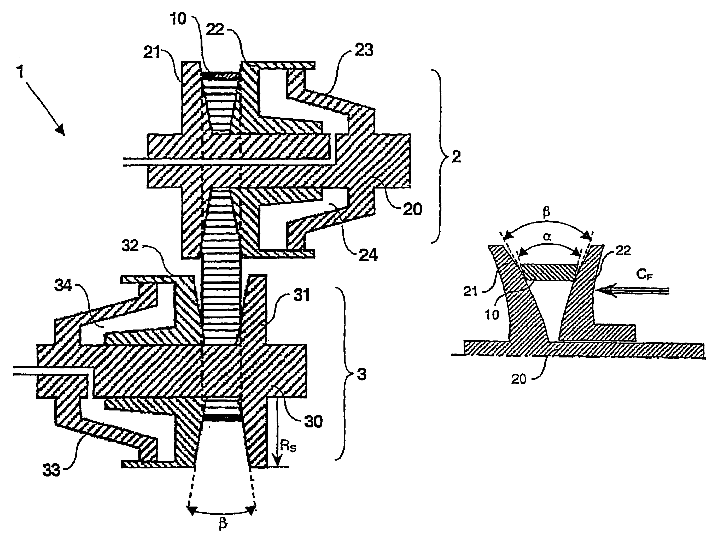
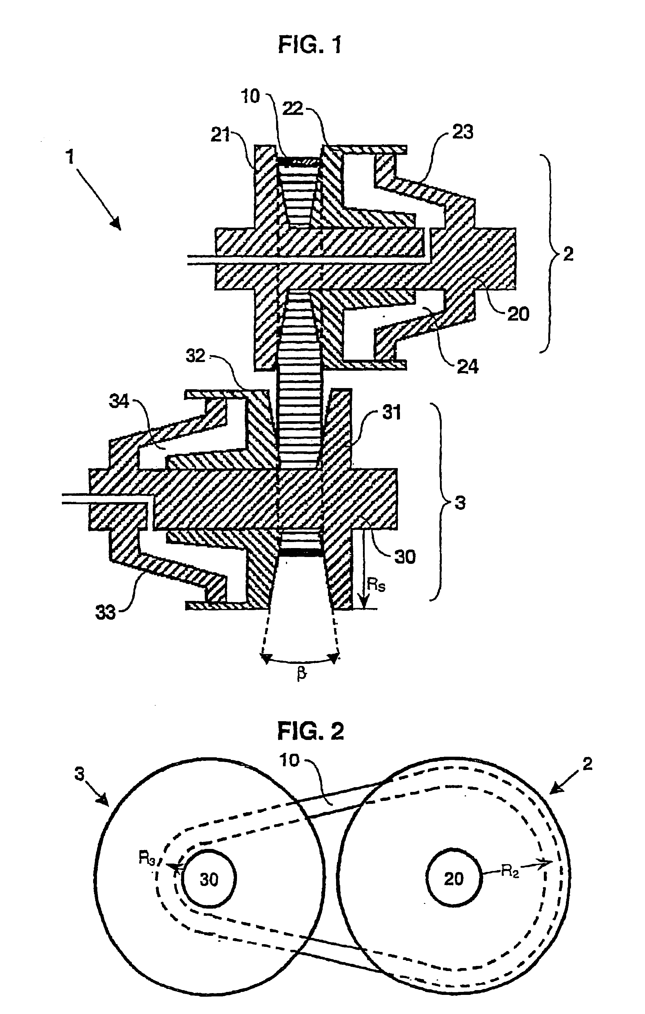
[0028]In FIG. 1 a CVT 1 according to the known art is shown. The CVT 1 comprises an input pulley 2 and an output pulley 3, each pulley 2; 3 comprising a set of two frusto-conical sheaves 21, 22; 31, 32 provided on an input pulley shaft 20 and on an output pulley shaft 30 respectively, and a flexible belt 10. The sheaves have a radial dimension RS. The sheaves 21, 22; 31, 32 of a pulley 2; 3 may be urged towards each other under the influence of a hydraulic pressure exerted in a piston / cylinder assembly 23, 24; 33, 34 associated with the respective pulley 2; 3. As a result thereof, a clamping force CF is effected between the flexible belt 10 and the pulley sheaves 21, 22; 31, 32, of each of the pulleys, so that torque may be transmitted between said pulley 2; 3 by the belt 10 through friction.

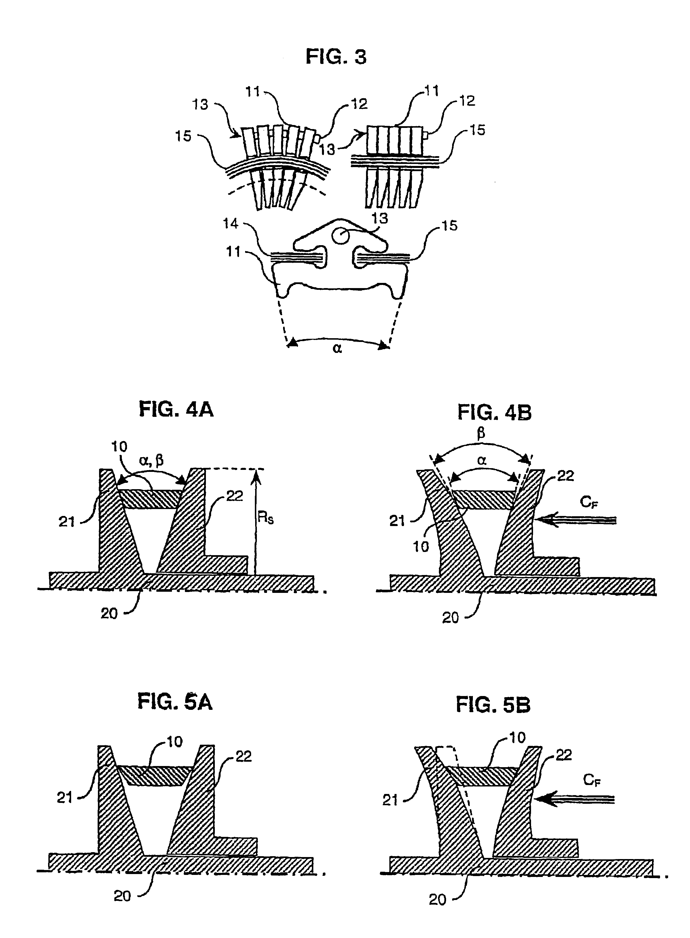
[0029]Each sheave 21, 22, 31, 32 has a sheave face, whereby the sheave faces of a pulley 2; 3 are mutually oriented at a pulley angle β, as indicated in FIG. 1, such that they define an essentia...


PUM


Abstract

A continuously variable transmission, provided with two adjustable pulleys, each pulley comprising a pair of mutually displaceable essentially frusto-conical pulley sheaves having a radial dimension provided on a pulley shaft, each sheave having a sheave face, whereby the sheave faces of a pulley are mutually oriented at a pulley angle, and with an endless flexible belt for transmitting torque comprising two lateral side faces, which are mutually oriented at a belt angle (alpha) such that the flexible belt tapers radially inwardly and which are intended for interacting with the sheave faces of a pulley under the influence of a clamping force to be exerted on the flexible belt by the sheaves. The belt angle is marginally, but notionally, larger than the pulley angle (beta) of at least one pulley for at least a substantial part of the radial dimension of the pulley sheaves.

Description

CROSS REFERENCE TO RELATED APPLICATIONS[0001]This patent results from a national stage of PCT / EP01 / 05921 filed May 23, 2001 and claims priority to European Application No. 00 / 201849.7 filed May 26, 2000.BRIEF DESCRIPTION OF THE INVENTION[0002]The present invention relates to a belt-type continuously variable transmission, alternatively denoted as a CVT, provided with an adjustable pulley and an endless flexible belt. The invention further relates to an endless flexible belt for torque transmission, such as a push-type drive belt, and to an adjustable pulley.DESCRIPTION OF THE RELATED ART[0003]The CVT of the present type is generally known, for example from EP-A-0.950.837, and comprises a first adjustable pulley, a second adjustable pulley and an endless flexible belt, such as a push-type drive belt known from EP-A-0.962.679, a chain and the like, for transmitting torque between the pulleys at a variable transmission ratio. In the known CVT, with the application of a clamping force, ...

Claims


Application Information

Patent Timeline
IPC IPC(8): F16H55/56F16H61/662F16G5/00F16G5/16F16H55/32F16H61/66F16H9/16
CPCF16G5/16F16H9/125F16H55/56F16H2061/66277
Inventor BRANDSMA, ARJENSMEETS, PAULUS MARIALAMERS, GERARDUS JOHANNES MARIA
Owner VAN DOORNES TRANSMISSIE BV
Why Eureka
Try Eureka