
Jack up workover rig with removable workover floor unit

a workover rig and floor unit technology, applied in the field of workover vessels, can solve the problems of high maintenance costs of both the workover vessel and the crew during workover, and the placement of the workover rig is more difficult, so as to reduce the cost of workover operations

Inactive Publication Date: 2005-08-09
BLAKE MICHAEL E
View PDF4 Cites 44 Cited by
  • Summary
  • Abstract
  • Description
  • Claims
  • Application Information

AI Technical Summary

Benefits of technology

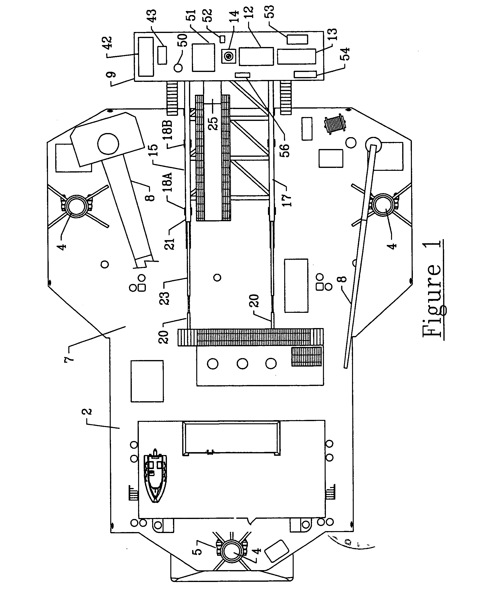
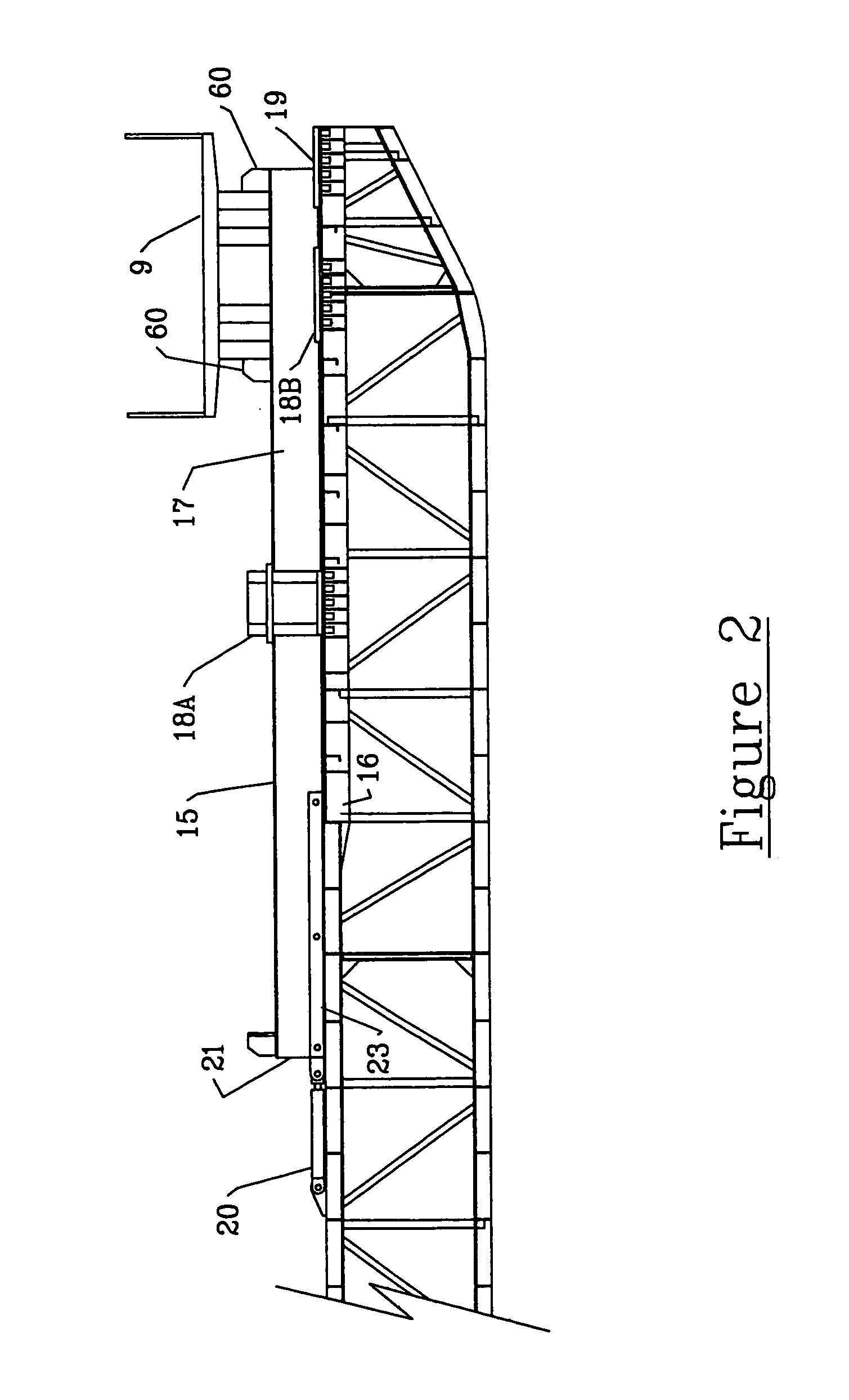
[0014]The location of the well on the platform will determine how the process will proceed from there. The vessel is provided with an extensible cantilevered frame. The workover floor unit is mounted to the distal end of this cantilevered frame. If the well is within the reach of the cantilevered frame, the vessel will simply extend the workover floor unit out over the well and work will proceed from workover floor unit with it still attached to extensible frame. The workover floor unit is configured to slide horizontally on the extensible frame to facilitate placement of the workover floor unit directly over the well.
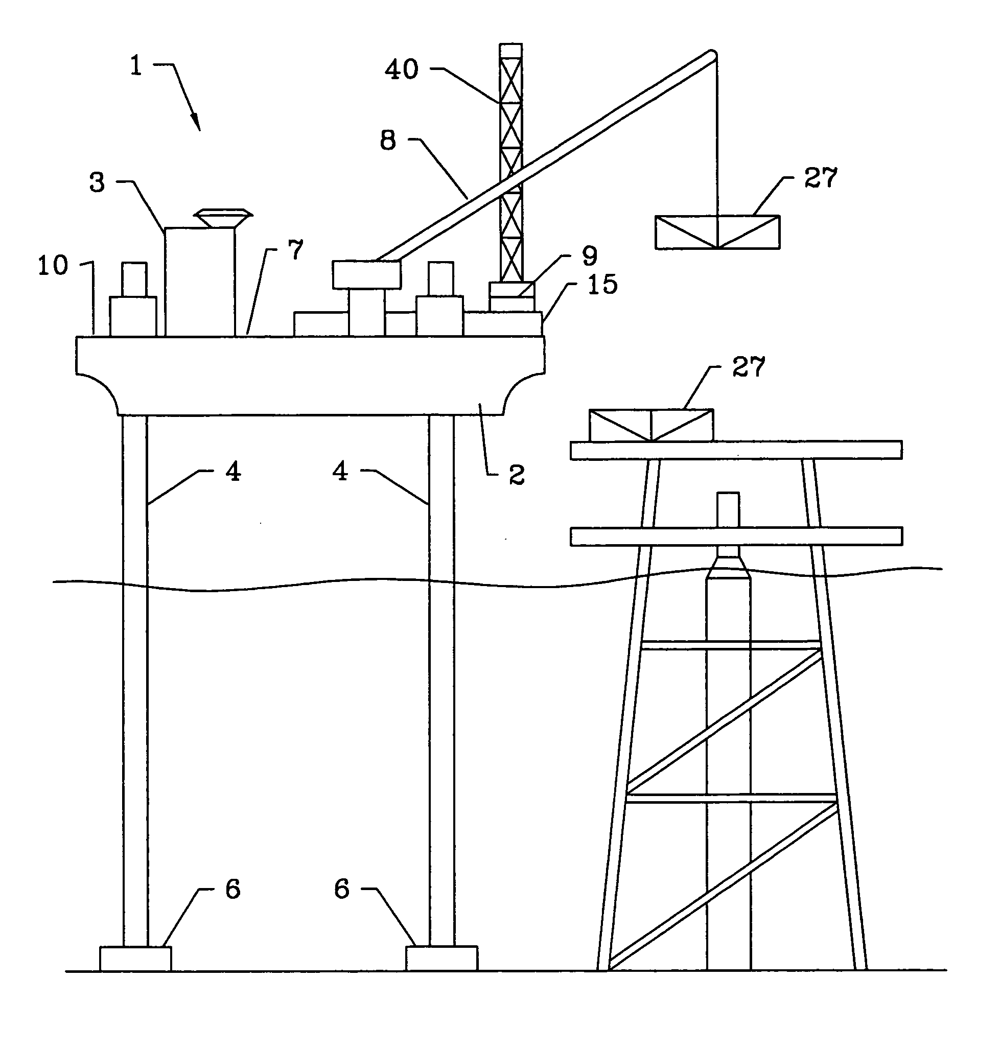
[0017]The second approach is particularly useful when the well to be serviced is beyond about thirty-six feet from the closest edge of the platform or if intervening structures prevent the above described “skid-off” procedure from being used. In this approach, the vessel is motored into place and jacked up until the vessel deck is at the desired height. Additionally, the vessel crane is used to position at least two skid beams on the platform on either side of the well. However, at this point, the workover floor unit is detached from the vessel. The crane is used to move the workover floor unit onto the skid beams and into position over the well. Once workover is complete, the crane can return the workover floor unit and the skid beams to the vessel. The foregoing procedures allow a single vessel to be used to provide workover service to platforms, substantially reducing the cost of workover operations to the well operator.

Problems solved by technology

In offshore wells, proper placement of the workover rig is more difficult.
Thus, maintaining both of these vessels and their crews during workover can be quite expensive.

Method used


Image

  • Jack up workover rig with removable workover floor unit
  • Jack up workover rig with removable workover floor unit
  • Jack up workover rig with removable workover floor unit

Examples


Embodiment Construction

[0036]The preferred embodiment comprises a jack-up workover rig 1 comprising a vessel 2 which may be a barge or a motor vessel. In either case, vessel 2 should have a thrust source 3 in the form of the primary engine on a motor vessel or a tug boat in the case of a barge. A bow thruster may be included as well to provide additional mobility to vessel 2.

[0037]A plurality of jack-up legs 4 are provided on vessel 2, typically three to four such legs 4 are provided and the preferred embodiment contains three. Jack-up legs 4 are provided with at least one jack up motor 5 configured to raise and lower legs 4. Preferably, each leg 4 has its own jack motor 5. Each leg 4 has a foot end 6. Preferably each foot end 6 is provided with a wide base to prevent leg 4 from sinking into the bed of the water body. When vessel 2 has motored into position, jack motors 5 will lower legs 4 until the foot ends 6 reach the bed of the water body. By continuing to extend legs 4 after foot ends 6 reach the bed...


PUM


Abstract

An offshore jack-up workover rig. The workover rig includes a vessel which may be self powered or powered by a tug. The vessel may be raised above the surface of a water body by extending the legs until they reach the water body bed and then continuing to extend the legs. The workover rig contains a workover floor unit which includes at least a drawworks, a drawworks motor, and a well aperture. The workover rig is detachably mounted on an extensible cantilevered frame. The frame may be extended to position the workover floor unit over an offshore platform to be serviced. The workover floor unit is also configured to mover laterally relative to the extensible frame. The vessel is also provided with a crane. The crane may be used to lift the detachable workover floor unit from the vessel and deposit it, including its equipment, on the platform.

Description

[0001]Priority claim: This application claims priority of, and hereby incorporates by reference the contents of U.S. Provisional Application No. 60 / 362,517, filed Mar. 6, 2002.BACKGROUND OF THE INVENTION[0002]1. Field of the Invention[0003]The invention relates to work over vessels in general and jack-up work over vessels in particular.[0004]2. Prior Art[0005]Oil and gas wells must be serviced occasionally for a number of reasons. For example, valves or seals may need to be replaced; flanges may need to be removed or installed in the wellhead; and blowout preventers may need to be removed, added, or serviced. The well may need production treatment, such as fracturing or acidizing, to stimulate the production of oil or gas therefrom. During treatment, the wellhead may need to be removed for well stimulating chemicals to be injected into the well. The packers and anchors in the well may need to be removed or reseated. Production tubing and well line tools may need to be removed from o...

Claims


Application Information

Patent Timeline
Patent Type & Authority Patents(United States)
IPC IPC(8): E21B15/00E21B15/02E02B17/02
CPCE02B17/021E21B15/02E02B2017/0056
Inventor BLAKE, MICHAEL E.
Owner BLAKE MICHAEL E
Learn More