Method for correcting stray radiation in an x-ray computed tomography scanner

a computed tomography and scanner technology, applied in tomography, image enhancement, instruments, etc., can solve the problems of unsatisfactory image artifacts, misinterpretations of tomographic images, and grave consequences to the extent of endangering the life of patients

Inactive Publication Date: 2005-08-02
SIEMENS HEALTHCARE GMBH
View PDF12 Cites 39 Cited by
  • Summary
  • Abstract
  • Description
  • Claims
  • Application Information

AI Technical Summary

Benefits of technology

[0014]In a first refinement of the method according to the invention, the at least one reference distribution of the stray radiation intensity is obtained from measured values of the reference intensity that are obtained by measuring radiation intensity outside the tomography measuring field. The fact that no primary radiation occurs outside the tomography measured field is thereby utilized. Measuring elements arranged there consequently detect only stray radiation. It is easily possible to determine a distribution of the stray radiation in the row direction, which is then used as the reference distribution.
[0016]In general, the spatial profile of the stray radiation can be represented by a comparatively low-frequency function. It is therefore sufficient to record measured values for the stray radiation in the row direction only in a relatively coarse array. In other words, the measured values of reference intensity are preferably obtained at measuring points that are situated at a mutual spacing in the row direction of the detector matrix and of which the number is smaller, in particular much smaller than the number of the detector elements per detector row. The reference distribution of the stray radiation intensity then can be easily obtained by interpolation of the measured values of reference intensity.

Problems solved by technology

Just like beam hardening effects scattering effects can cause undesired image artifacts in the reconstructed tomographic image of a transirradiated layer of a patient or some other object under examination.
These image artifacts simulate structures corresponding to no real anatomy of the object under examination, and therefore lead to misinterpretations of the tomographic image.
Particularly in the medical sector, such misinterpretations can have grave consequences to the extent of endangering the life of the patient.
However, tungsten has the disadvantage of being very expensive.
This cost disadvantage is particularly significant when the detector is a detector matrix with a multiplicity of detector elements arranged next to one another in a number of superimposed detector rows.

Method used


Image

  • Method for correcting stray radiation in an x-ray computed tomography scanner
  • Method for correcting stray radiation in an x-ray computed tomography scanner
  • Method for correcting stray radiation in an x-ray computed tomography scanner

Examples


Embodiment Construction

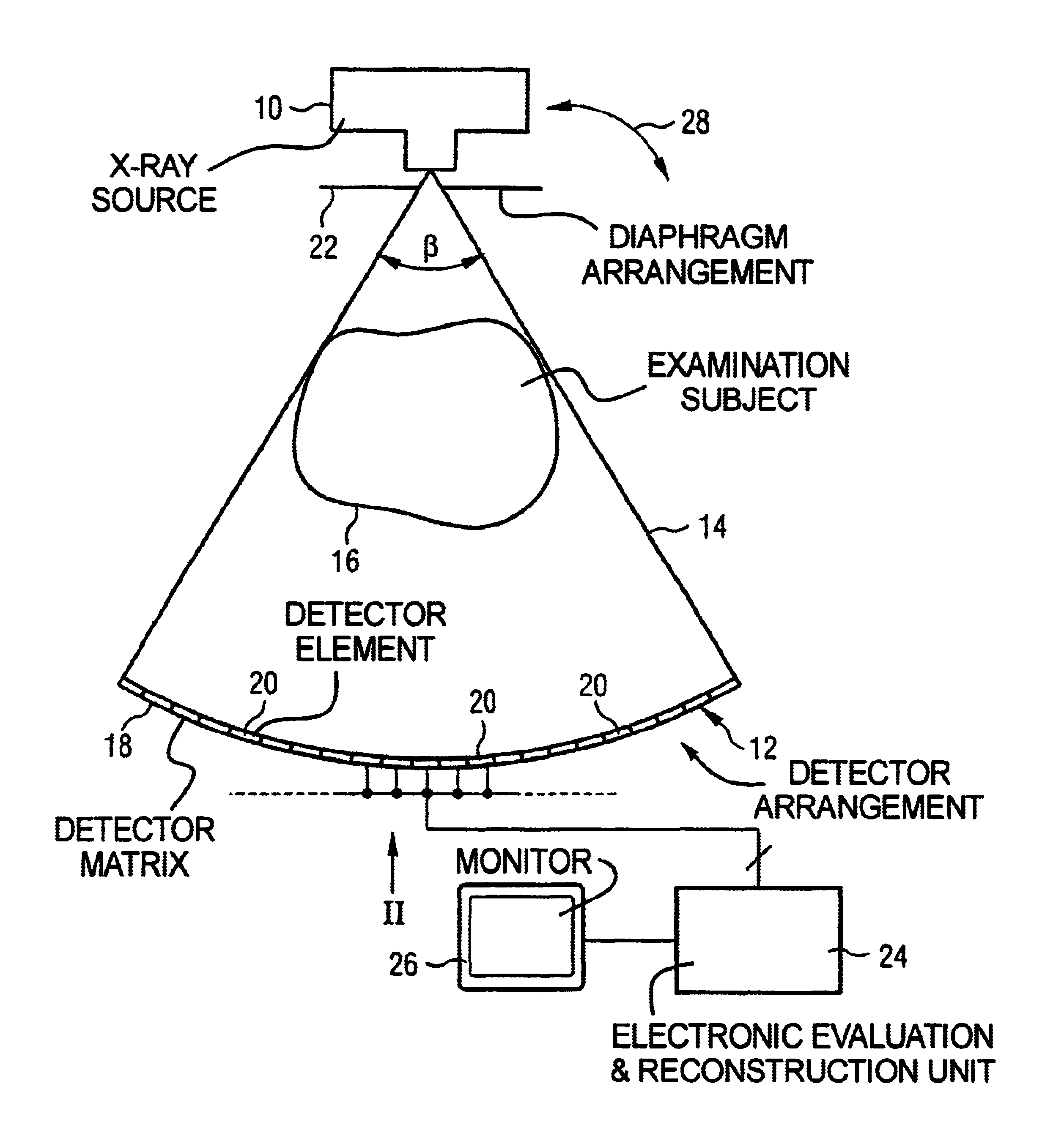
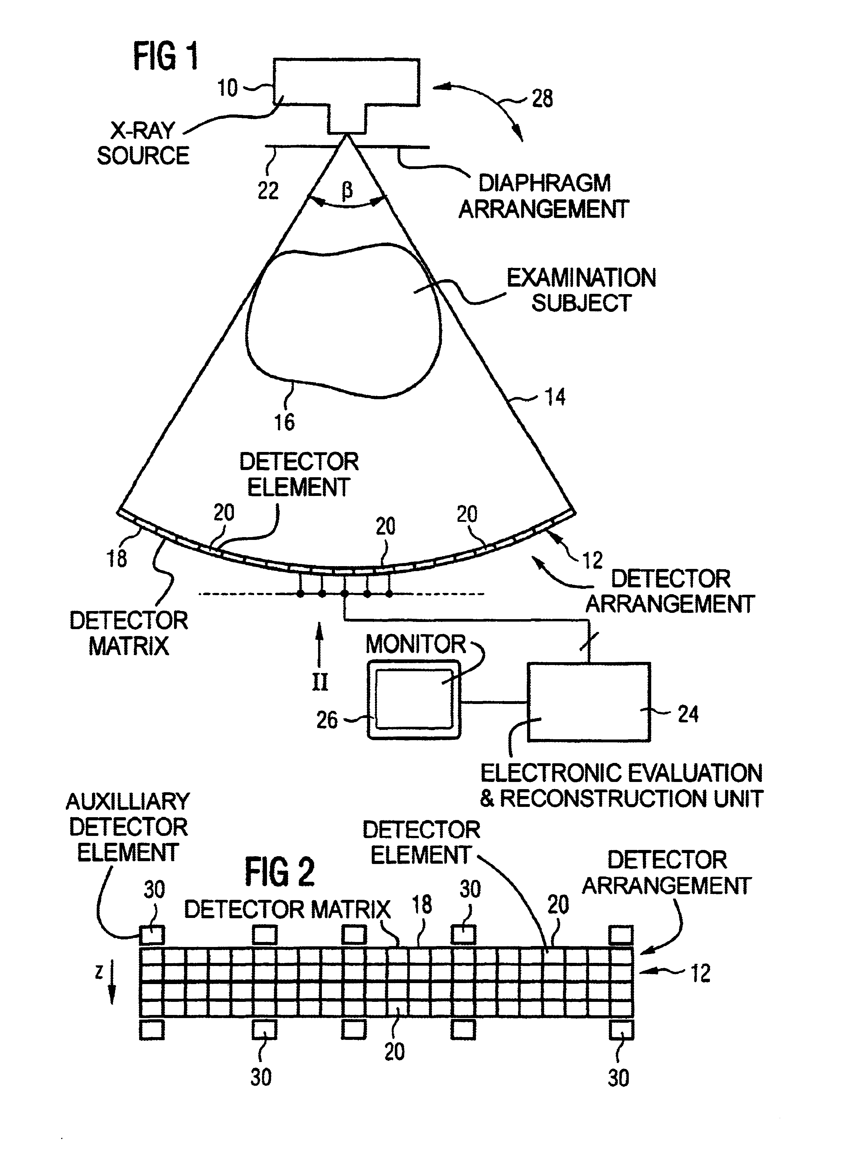
[0031]The CT scanner shown in the figures has an X-ray source 10 and a detector arrangement 12. The X-ray source 10 emits X-ray radiation in the shape of a fan, as indicated at 14. An object under examination 16 arranged in the beam path between the X-ray source 10 and the detector arrangement 12 is penetrated by the X-ray radiation. The detector arrangement 12 detects the X-ray radiation downstream of the object under examination 16. Specifically, the detector arrangement 12 has a detector matrix 18 composed of a multiplicity of detector elements 20 that are distributed over a number of adjacent rows and are arranged next to one another in each row in the direction of a fan angle β. Four such detector rows are shown as an example in FIG. 2; however, the number of the detector rows can differ therefrom as desired and can be 8, 16 or 24, instead, for example. The size of the beam fan 14 in the direction of the fan angle β can be set by means of a diaphragm arrangement 22 that is arra...


PUM

PropertyMeasurementUnit
depthaaaaaaaaaa
frequencyaaaaaaaaaa
spatial frequencyaaaaaaaaaa

Abstract

In a method for correcting for stray radiation in measured intensity values, the measured intensity values are obtained in an X-ray computed tomography scanner by means of a detector matrix that is situated in a tomography measuring field of the computer tomography scanner and has a multiplicity of detector elements arranged next to one another in a number of adjacent detector rows. At least one reference distribution of the stray radiation intensity is determined in the row direction of the detector matrix, and a stray radiation component of each measured value of intensity is determined starting from this at least one reference distribution, and the measured intensity values are corrected as a function of their respective stray radiation component. In this case, the stray radiation component of the measured values of intensity of at least a fraction of the detector rows is determined by using a recursion method on the basis of the reference distribution.

Description

BACKGROUND OF THE INVENTION[0001]1. Field of the Invention[0002]The present invention relates to the correction of image artifacts in X-ray computed tomography that are caused by stray radiation.[0003]2. Description of the Prior Art[0004]Just like beam hardening effects scattering effects can cause undesired image artifacts in the reconstructed tomographic image of a transirradiated layer of a patient or some other object under examination. These image artifacts simulate structures corresponding to no real anatomy of the object under examination, and therefore lead to misinterpretations of the tomographic image. Particularly in the medical sector, such misinterpretations can have grave consequences to the extent of endangering the life of the patient.[0005]In order to suppress the stray radiation component in the radiation intensity values measured with a detector, it is known to collimate at the detector side the X-ray radiation transirradiating the object under examination. As a r...

Claims


Application Information

Patent Timeline
Patent Type & Authority Patents(United States)
IPC IPC(8): G01N23/04G01N23/02G06T5/00H05G1/26H05G1/00A61B6/03
CPCA61B6/4233A61B6/5282A61B6/585G01N23/046H05G1/26G06T5/003A61B6/032A61B6/4085G06T2207/10081G01N2223/419
Inventor BRUDER, HERBERT
Owner SIEMENS HEALTHCARE GMBH
Why Eureka
Try Eureka