
Method and system for operating a generator using a dynamic capability curve

a technology of dynamic capability and generator, applied in the direction of electric generator control, dynamo-electric converter control, instruments, etc., can solve the problems of increasing the stator and field current capability limits, under-utilization of the power-generating capability of the generator, and typically limited power produced by the generator. to achieve the effect of rapid and accurate transmission of information to the operator

Inactive Publication Date: 2005-08-02
SIEMENS ENERGY INC
View PDF15 Cites 29 Cited by
  • Summary
  • Abstract
  • Description
  • Claims
  • Application Information

AI Technical Summary

Benefits of technology

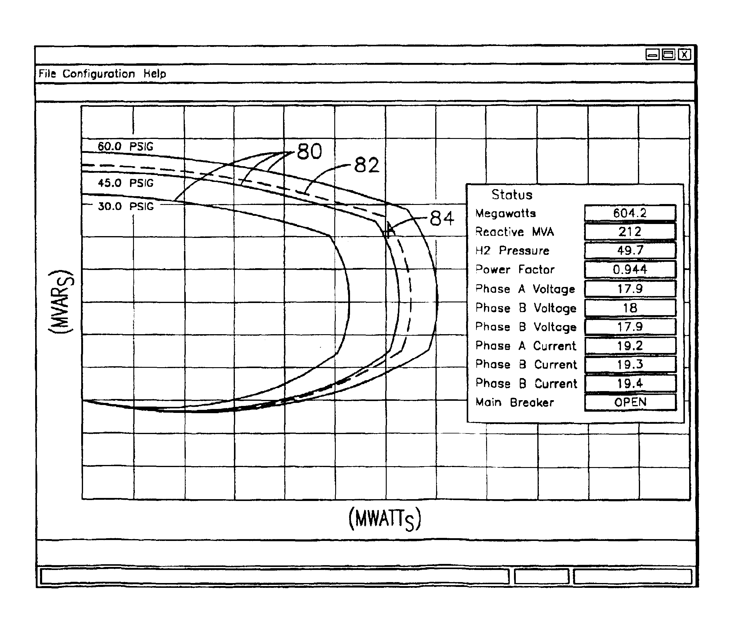
[0005]It has been recognized by the inventor of the present invention that a capability curve that dynamically varies in correspondence with the actual pressure of the cooling fluid is needed. This would allow the operator to accurately and consistently adjust at least one operational parameter of the generator to accurately match the present operational conditions of the generator. In view of the long-standing familiarity of the operators with the static capability curves, it would be desirable to display the dynamic capability curve jointly with the static curves. Moreover, in order to rapidly and accurately convey information to the operator regarding the operational performance of the generator, it would be also desirable to graphically and distinctively display the dynamic capability curve of the generator relative to the static curves.
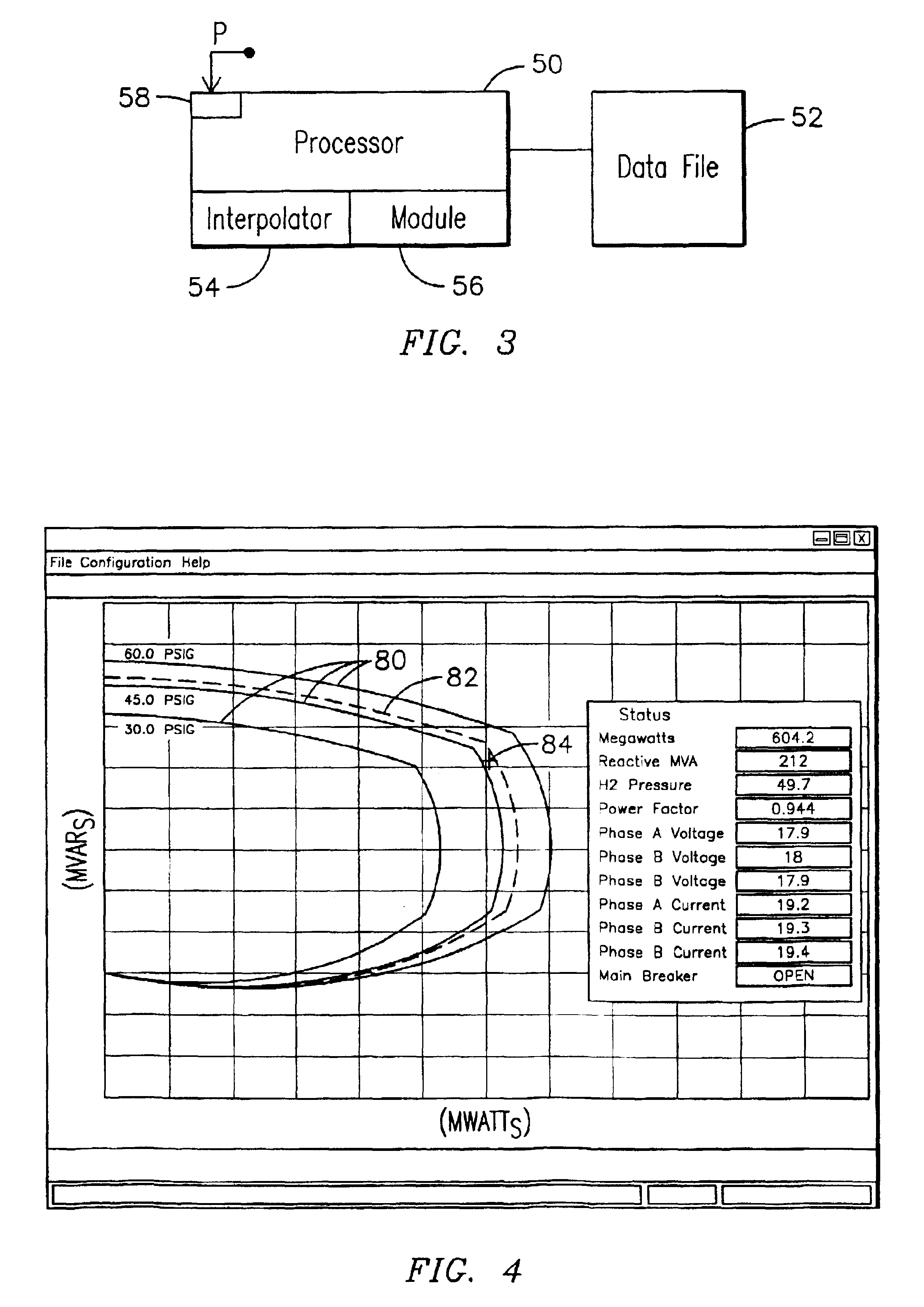
[0006]Generally, the present invention fulfills the foregoing needs by providing in one aspect thereof, a method for operating a generator using a dynamic capability curve. The method allows providing a family of static capability curves corresponding to nominal reference levels of pressure of a fluid for cooling the generator. The method further allows acquiring data indicative of the actual pressure of the cooling fluid. A dynamic capability curve is generated to be responsive to the actual pressure of the cooling fluid. The family of static capability curves may be displayed relative to the dynamic capability curve, thereby allowing the operator to monitor and control the operation of the generator based on the actual pressure of the cooling fluid and further in view of at least one of the nominal reference levels of pressure for the cooling fluid.
[0007]In another aspect thereof, the present invention further fulfills the foregoing needs by providing a system for operating a generator using a dynamic capability curve. The system includes a data file configured to store a family of static capability curves corresponding to nominal reference levels of pressure of a fluid for cooling the generator. A device is used to acquire data indicative of the actual pressure of the cooling fluid. A processor is configured to generate a dynamic capability curve responsive to the actual pressure of the cooling fluid. The processor is further configured to access the data file for displaying the family of static capability curves relative to the dynamic capability curve, thereby allowing the operator to monitor and control the operation of the generator based on the actual pressure of the cooling fluid and further in view of at least one of the nominal reference levels of pressure for the cooling fluid.

Problems solved by technology

The amount of power produced by the generator is typically limited by the design characteristics of the generator.
Increasing the gas pressure, and thus the flow of the cooling fluid, may increase the stator and field current capability limits.
Depending on how far below the rated hydrogen pressure the generator is operated, there may be significant underutilization of the power-generating capability of the generator.

Method used


Image

  • Method and system for operating a generator using a dynamic capability curve
  • Method and system for operating a generator using a dynamic capability curve
  • Method and system for operating a generator using a dynamic capability curve

Examples


Embodiment Construction

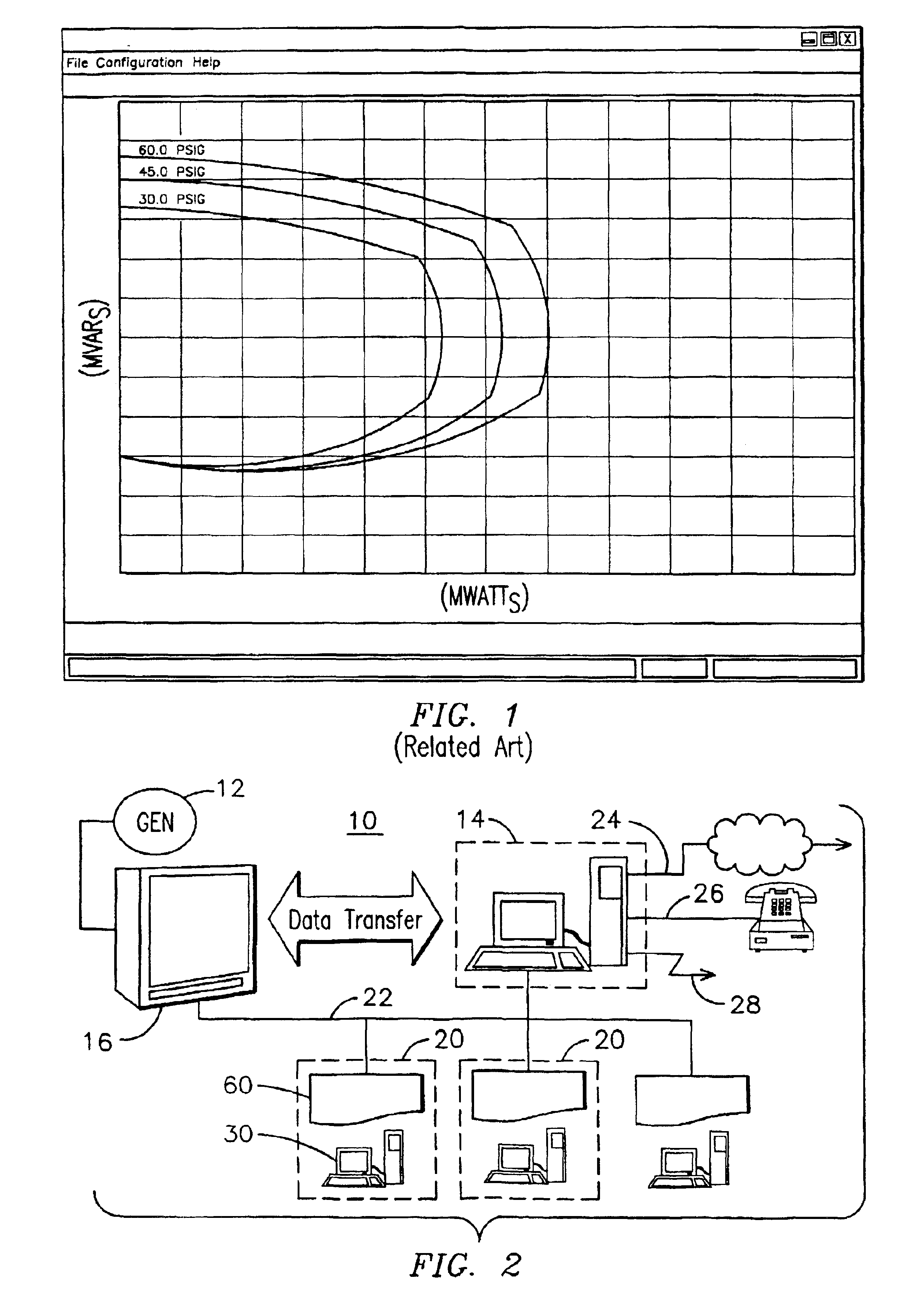
[0015]A capability curve is a curve that defines the boundaries of the area on a power flow diagram, such as real and reactive power flow diagram, within which a dynamoelectric machine, such as a generator, may be safely operated. The inventor of the present invention has innovatively recognized a way of integrating in a user-friendly manner techniques familiar to operators of the machines with techniques that allow one to more closely track the actual operational conditions of the machine so that the operator is able to rapidly and accurately asses this information without having to undergo any burdensome training, or without having to re-develop new instructional materials.

[0016]FIG. 2 represents an exemplary data communications system 10 that may be used for communicating information to users, such as operators, service personnel, and engineering staff, regarding the operational performance of a generator 12. A server 14 may be connected to a plant computer system 16 to communica...


PUM


Abstract

Method and system are provided for operating a generator using a dynamic capability curve. In one embodiment, the method allows providing a family of static capability curves corresponding to nominal reference levels of pressure of a fluid for cooling the generator. The method further allows acquiring data indicative of the actual pressure of the cooling fluid. A dynamic capability curve is generated to be responsive to the actual pressure of the cooling fluid. The family of static capability curves may be displayed relative to the dynamic capability curve, thereby allowing the operator to monitor and control the operation of the generator based on the actual pressure of the cooling fluid and further in view of at least one of the nominal reference levels of pressure for the cooling fluid.

Description

FIELD OF THE INVENTION[0001]The present invention relates in general to electrical generators, and, more particularly, to method and system for operating a generator using a dynamic capability curve.BACKGROUND OF THE INVENTION[0002]A generator is one key piece of equipment of a power generation plant and allows converting mechanical energy to electrical energy. An AC generator comprises two primary components: a rotor and a stator. The rotor is made up of electrically conductive coils that form a rotor winding. The stator is also made up of coils that form a stator winding. Mechanical energy turns the rotor relative to the stator while a field current is passed through the rotor winding to induce a voltage on the stator winding. The amount of power produced by the generator is typically limited by the design characteristics of the generator. For example, one needs to consider heating effects that may develop due to increased levels of currents passing through the stator or the rotor...

Claims


Application Information

Patent Timeline
Patent Type & Authority Patents(United States)
IPC IPC(8): G01R11/32G01R11/00H02H7/06H02P11/00H02P9/10H02P9/00H02P9/14
CPCH02P9/006H02P31/00
Inventor THOMPSON, EDWARD DAVID
Owner SIEMENS ENERGY INC
Learn More