
Multilayer capacitor

a multi-layer capacitor and capacitor technology, applied in the field of multi-layer capacitors, can solve the problems of increasing noise, increasing noise, and multi-layer capacitors having a large esl such as a conventional one cannot respond to the recent trend toward a higher frequency

Inactive Publication Date: 2005-07-26
TDK CORPARATION
View PDF12 Cites 42 Cited by
  • Summary
  • Abstract
  • Description
  • Claims
  • Application Information

AI Technical Summary

Benefits of technology

[0012]In consideration of the above-described situation, it is an object of the present invention to provide a multilayer capacitor capable of reducing structural defects or the like to enhance reliability and reducing ESL to allow more effective execution of a noise countermeasure in a high frequency range.
[0016]Therefore, since the leadout portion of the second internal conductor connected to the grounding terminal electrode is divided into a plurality of portions, the dielectric sheets come in contact with each other also in gaps between the divided leadout portions. Owing to the increase in joining area, this structure prevents the joining strength between the dielectrics from deteriorating, compared with the structure such that the width dimension of the leadout portion of the second conductor is simply made larger.
[0017]As a result, structural defects such as a crack do not occur in a portion where the leadout portion exists at the ceramic sintering time for processing the stacked dielectric sheets into a multilayer body, and in addition, the element strength of the multilayer body is increased to enhance resistance against an external stress such as the deflection of a substrate, leading to enhanced reliability of the multilayer capacitor.
[0018]Therefore, according to the multilayer capacitor of this mode, dividing the readout portion into the plural portions reduces the structural defects or the like to enhance reliability, and reduces ESL to allow more effective execution of a noise countermeasure in a high frequency range.
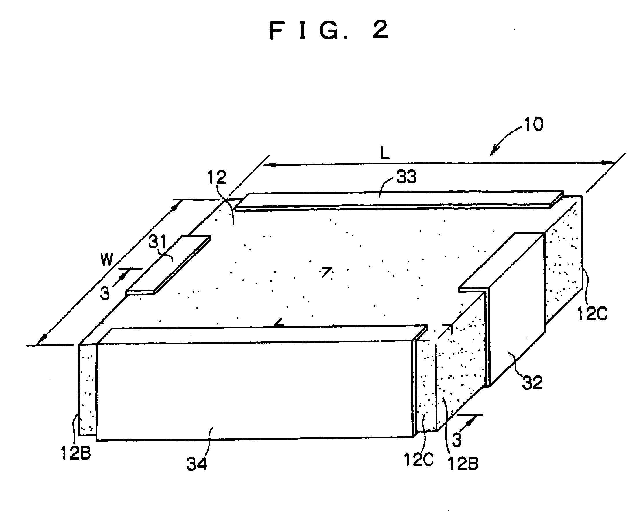
[0022]Therefore, it is possible to not only obtain the same operation as that of the multilayer capacitor of the above-described mode but also downsize the multilayer capacitor owing to the optimum arrangement of these terminal electrodes on the side faces of the capacitor body.

Problems solved by technology

However, ESL (equivalent series inductance) which is a parasitic component of a multilayer capacitor acts as an obstruction to an effect of filtering out noises in a high-frequency range, and thus this effect is becoming less sufficient as the operating frequency or the like of the equipment is becoming still higher.
In other words, multilayer capacitors having a large ESL such as a conventional one cannot respond to the recent tendency toward a higher frequency.
However, since the frequency handled in recent equipment has become remarkably high, which further increases noises, and the lower power consumption of the equipment lowers operating voltage, noise resistance of the equipment is deteriorating.
Moreover, further reduction in ESL is an important issue also for a multilayer feedthrough capacitor in order to cope with such a current situation.
As a result, structural defects such as a crack may occur in these portions or the element strength of the multilayer body may be significantly lowered at the time of ceramic sintering for processing the dielectrics to the multilayer body.
Accordingly, resistance against an external stress such as the deflection of a substrate deteriorates, giving rise to the concern about reliability deterioration.

Method used


Image

  • Multilayer capacitor
  • Multilayer capacitor
  • Multilayer capacitor

Examples


Embodiment Construction

[0031]Hereinafter, a first embodiment of the multilayer capacitor according to the present invention will be described based on the drawings.

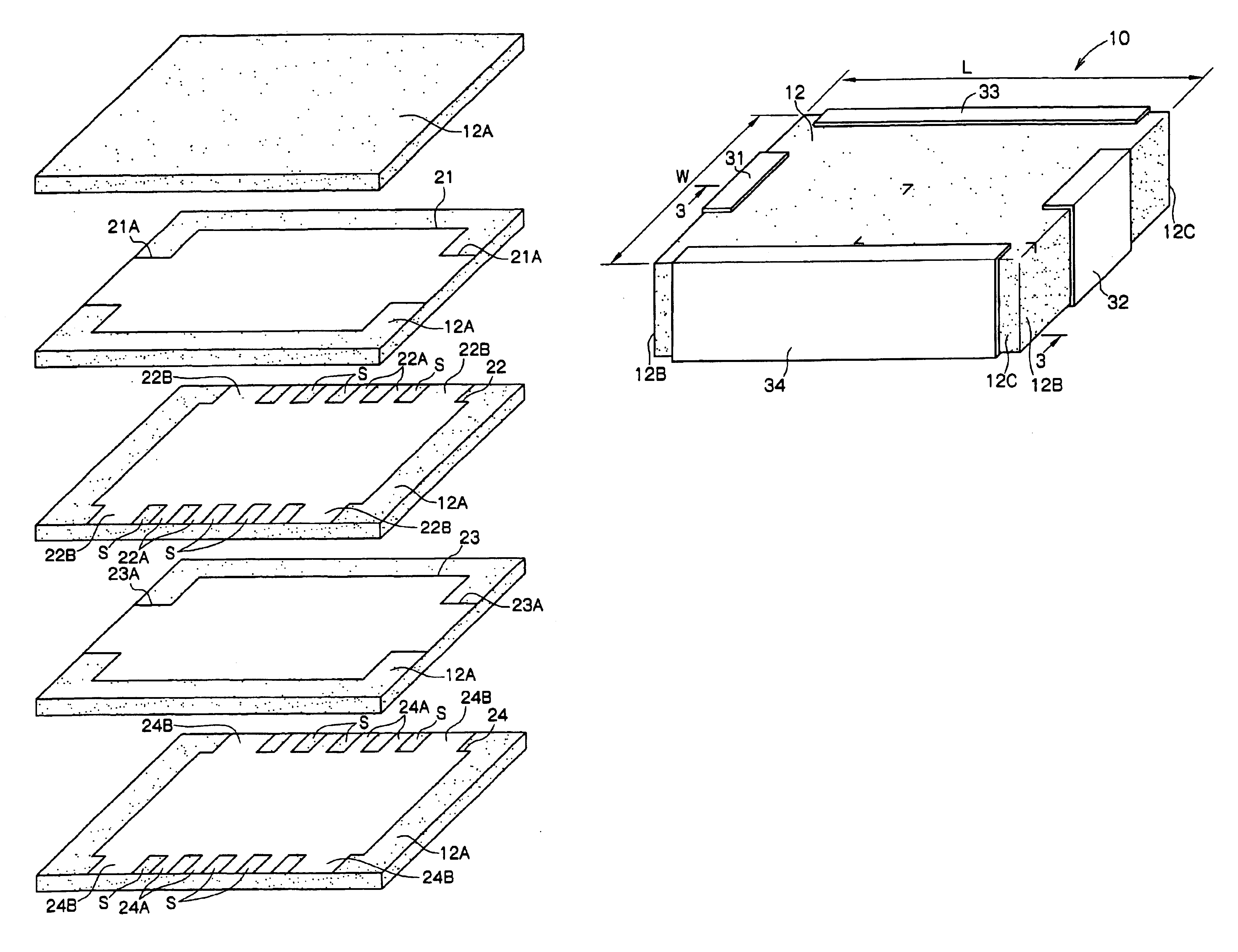
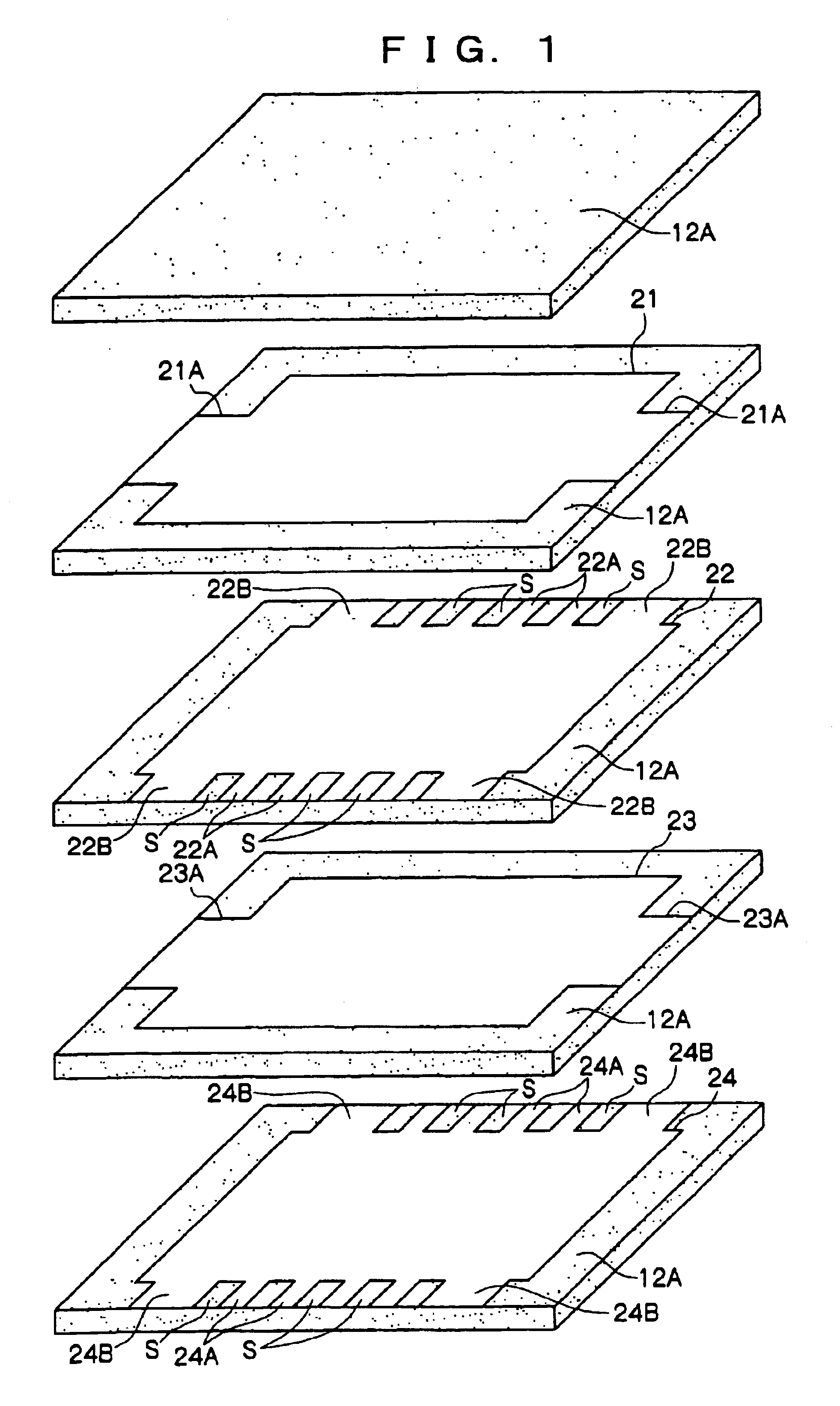
[0032]As shown in FIG. 1 to FIG. 3, a multilayer feedthrough capacitor 10 being the multilayer capacitor according to the first embodiment of the present invention includes as a major portion thereof a dielectric element 12 which is a multilayer body in a rectangular parallelepiped shape which is obtained by sintering a stack of a plurality of ceramic green sheets being dielectric sheets.

[0033]As shown in FIG. 1 and FIG. 3, an internal electrode 21 extending from right to left of FIG. 1 of the dielectric element 12 is disposed at a predetermined height position in the dielectric element 12. In the dielectric element 12, an internal electrode 22 extending from the near side to the back side of FIG. 1 of the dielectric element 12 is also disposed under the internal electrode 21 across a ceramic layer 12A being the sintered ceramic green sheet.

[00...


PUM

PropertyMeasurementUnit
widthaaaaaaaaaa
dielectricaaaaaaaaaa
widthaaaaaaaaaa

Abstract

A multilayer capacitor includes: a capacitor body formed by stacking a plurality of dielectric sheets with a first internal conductor and a second internal conductor sandwiching at least one of the dielectric sheets; a signal terminal electrode disposed on a side face of the capacitor body and connected to the first internal conductor; a leadout portion led out from the second internal conductor in a plurally divided form; and a grounding terminal electrode disposed on a side face of the capacitor body and connected to the second internal conductor via the leadout portion. Therefore, it is possible to reduce structural defects or the like to enhance reliability and to reduce ESL to allow more effective execution of a noise countermeasure in a high frequency range.

Description

BACKGROUND OF THE INVENTION[0001]1. Field of the Invention[0002]The present invention relates to a multilayer capacitor used as a noise filter or the like capable of reducing structural defects or the like to enhance reliability and reducing equivalent series inductance (ESL) to allow more effective execution of a noise countermeasure in a high frequency range, and more particularly, to that suitable for use in a circuit of data processing equipment and communication equipment.[0003]2. Description of the Related Art[0004]Data processing equipment and communication equipment in recent years are mostly digitalized, and further, the frequency of digital signals handled in these kinds of equipment is becoming higher in accordance with the increased speed of data processing capability. Accordingly, noises generated from these equipments similarly tend to increase in a high-frequency range. As a noise countermeasure, many of these equipments use electronic components for preventing electr...

Claims


Application Information

Patent Timeline
Patent Type & Authority Patents(United States)
IPC IPC(8): H01G2/00H01G4/35H01G2/20H01G4/30H01G4/005H01G4/228H01G4/12H01G4/012H01G4/232
CPCH01G4/012H01G4/232H01G4/30H01G4/35H01G4/12
Inventor TOGASHI, MASAAKI
Owner TDK CORPARATION
Learn More