Optical interleaver/deinterleaver device having an array of micro-mirrors

Inactive Publication Date: 2005-07-26
II VI DELAWARE INC
View PDF22 Cites 27 Cited by
  • Summary
  • Abstract
  • Description
  • Claims
  • Application Information

AI Technical Summary

Benefits of technology

[0014]An object of the present invention is to provide a reconfigurable optical interleaver / deinterleaver having a spatial light modulator that includes a micro-mirror device having an array of micro-mirrors, wherein a plurality of micro-mirrors direct the optical channels of the WDM input signal to separate the WDM signal into a pair of optical signals having channels spectrally spaced, or combining a pair of optical signals having spaced channels into a single WDM signal, which advantageously permits the interleaver / deinterleaver, to be reconfigurable by changing a switching algorithm that drives the micro-mirrors, without having to change the hardware configuration.

Problems solved by technology

One disadvantage of Bragg grating technology is that it requires many discrete gratings and / or switches, which makes a 40 or 80 channel device quite expensive.
One issue with the above optical MEMS device is that it is not “channel plan independent”.
Another concern is that if the absolute value of a channel wavelength changes, a respective optical signal may begin to hit an edge of a corresponding mirror leading to large diffraction losses.

Method used


Image

  • Optical interleaver/deinterleaver device having an array of micro-mirrors
  • Optical interleaver/deinterleaver device having an array of micro-mirrors
  • Optical interleaver/deinterleaver device having an array of micro-mirrors

Examples


Embodiment Construction

FIGS. 3-7: The Basic Invention

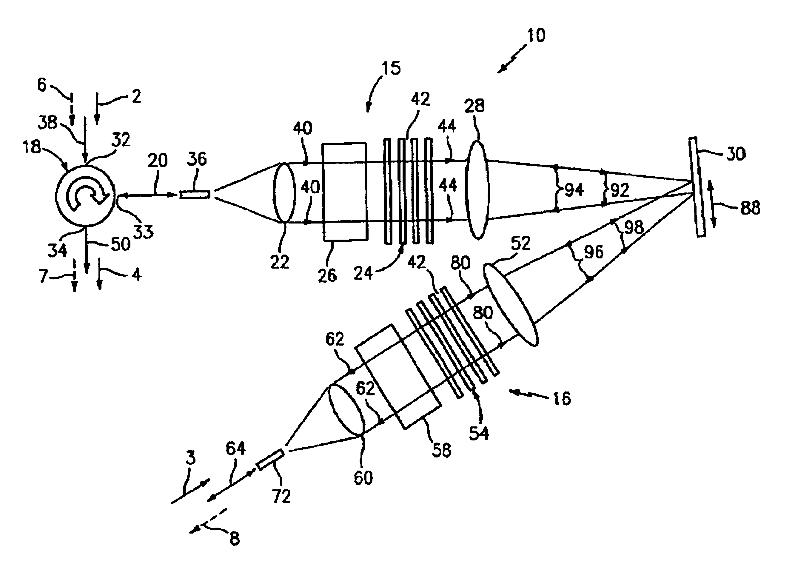
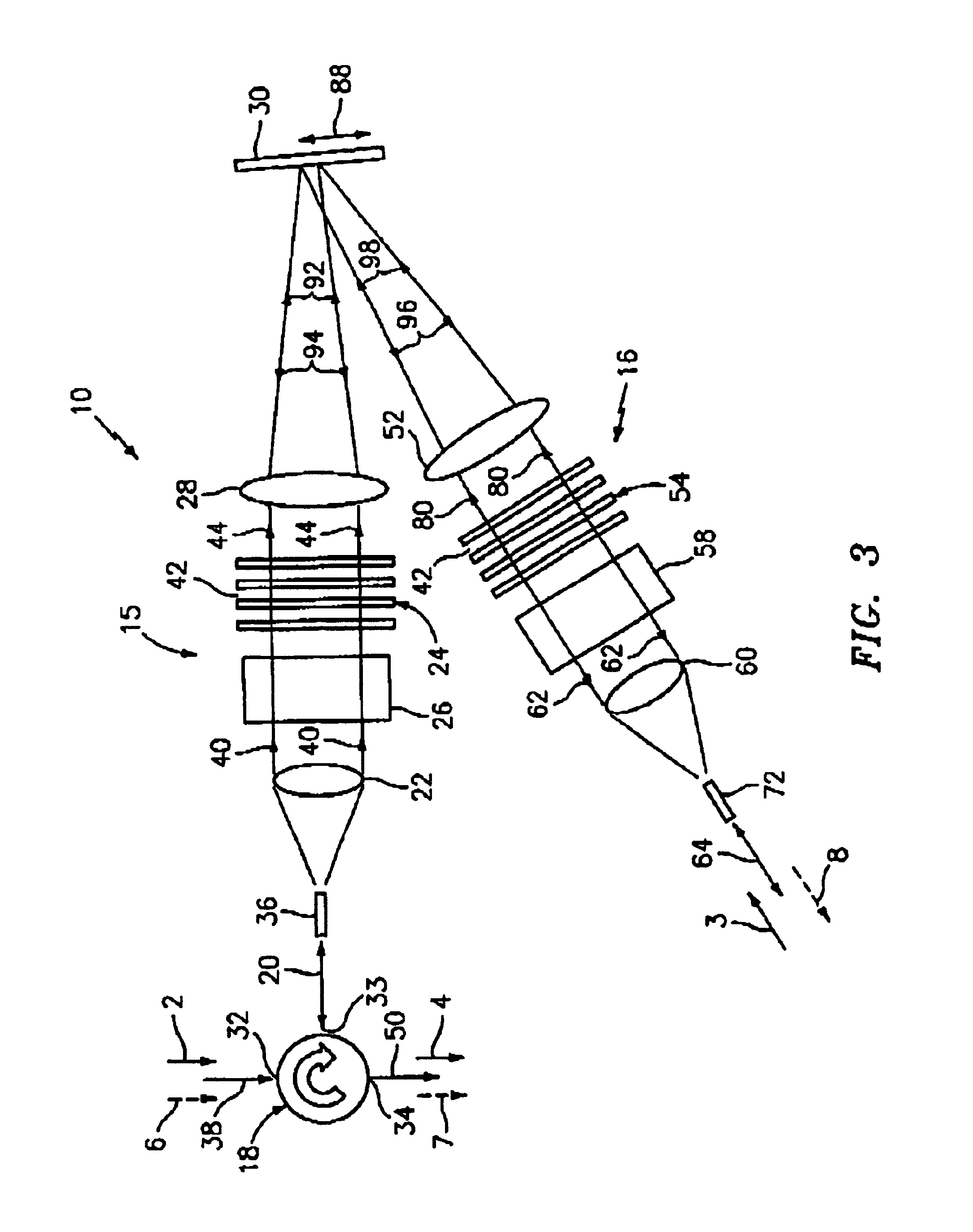
[0072]FIGS. 3-7 show an embodiment of the basic invention which features an optical interleaver / de-interleaver device generally indicated as 10 including an optical arrangement 15, 16 for receiving a pair of optical input signals, each optical input signal having a respective set of at least one optical wavelength band or channel, and including a spatial light modulator 30 having a micro-mirror device (FIGS. 5-8) with an array of micro-mirrors 84 for reflecting the two or more optical signals provided thereon. The optical arrangement 15, 16 comprises a free optic configuration having one or more light dispersion elements for separating the optical input signal(s) so that each optical band or channel is reflected by a respective plurality of micro-mirrors 100, 101, 102, 103 (FIG. 8) to selectively either combine two respective sets of the at least one optical band or channel into one optical output signal, or de-combine one set of the one optical channel...


PUM


Abstract

A reconfigurable optical interleaver / deinterleaver device combines / separates a pair of optical input signals from and / or to an optical WDM input signal. The interleaver device includes a spatial light modulator having a micro-mirror device with a two-dimensional array of micro-mirrors that flip between first and second positions in a “digital” fashion in response to a control signal provided by a controller in accordance with a switching algorithm and an input command. A pair of collimators, diffraction gratings and Fourier lens collectively collimate, separate and focus the optical input channels and optical add channels onto the array of micro-mirrors. Each optical channel is focused on a plurality of micro-mirrors of the micro-mirror device, which effectively pixelates the optical channels.

Description

CROSS REFERENCE TO RELATED APPLICATIONS[0001]This application claims benefit to provisional patent application Ser. No. 60 / 325,064 (CC-0397), entitled “Optical Interleaver / De-interleaver Having an Array of Micromirrors”, filed Sep. 25, 2001, and is a continuation-in-part of patent application Ser. No. 10 / 115,647 (CC-0461), filed Apr. 3, 2002, as well as a continuation-in-part of patent application Ser. No. 10 / 120,617 (CC-0461), filed Apr. 11, 2002, which are all hereby incorporated by reference in their entirety.[0002]This application filed concurrently with the same identified by Express mail nos. EV 137 071 802 US (CC-0544), EV 137 071 793 US (CC-0545), and EV 137 071 816 US (CC-0546), which are also hereby incorporated by reference in their entirety.BACKGROUND OF THE INVENTION[0003]1. Technical Field[0004]The present invention relates to a tunable optical device, and more particularly to an optical interleaver / deinterleaver including an array of micro-mirrors to optically separat...

Claims


Application Information

Patent Timeline
IPC IPC(8): G02B27/10G02B26/08G02B6/26G02B6/34G02B6/42
CPCG02B6/262G02B6/2931G02B6/29386G02B6/29395G02B26/0841G02B27/1006G02B27/1086G02B6/4226
Inventor MOON, JOHN A.KERSEY, ALAN D.DAWSON, JAY W.DUNPHY, JAMES R.PINTO, JOSEPHO'KEEFE, CHRISTIANSZCZEPANEK, PAUL
Owner II VI DELAWARE INC
Why Eureka
Try Eureka