PDL mitigation structure for diffractive MEMS and gratings

a technology of diffractive mems and structures, applied in the field of apparatus for mitigating, can solve the problems of degrading the quality of transmission and reducing the pdl in the devi

Active Publication Date: 2005-07-26
SILICON LIGHT MACHINES CORP
View PDF879 Cites 9 Cited by
  • Summary
  • Abstract
  • Description
  • Claims
  • Application Information

AI Technical Summary

Benefits of technology

[0010]Embodiments of the present invention include a diffractive MEMS for modulating or switching an incident beam of light. The diffractive MEMS includes a plurality of elements, each element including a first end, a second end, a first non-linear side, a second non-linear side, and a light reflective planar surface. The light reflective planar surfaces of the plurality of elements lie in one or more parallel planes. The elements are preferably arranged parallel to each other. The modulator also includes a support structure to maintain a position of each element relative to each other and to enable movement of selective ones of the plurality of elements in a direction normal to the one or more parallel planes of the plurality of elements. The plurality of elements are preferably moved between a first modulator configuration wherein the plurality of elements act to reflect the incident beam of light as a plane mirror, and a second modulator configuration wherein the plurality of elements act to diffract the incident beam of light.

Problems solved by technology

Unfortunately, when arbitrarily polarized light impinges on the diffractive light modulator depicted in FIGS. 2 and 3, different polarization states interact with the diffractive light modulator differently.
This results in the degradation of the quality of the transmission and therefore PDL in the device must be minimized.

Method used


Image

  • PDL mitigation structure for diffractive MEMS and gratings
  • PDL mitigation structure for diffractive MEMS and gratings
  • PDL mitigation structure for diffractive MEMS and gratings

Examples


Embodiment Construction

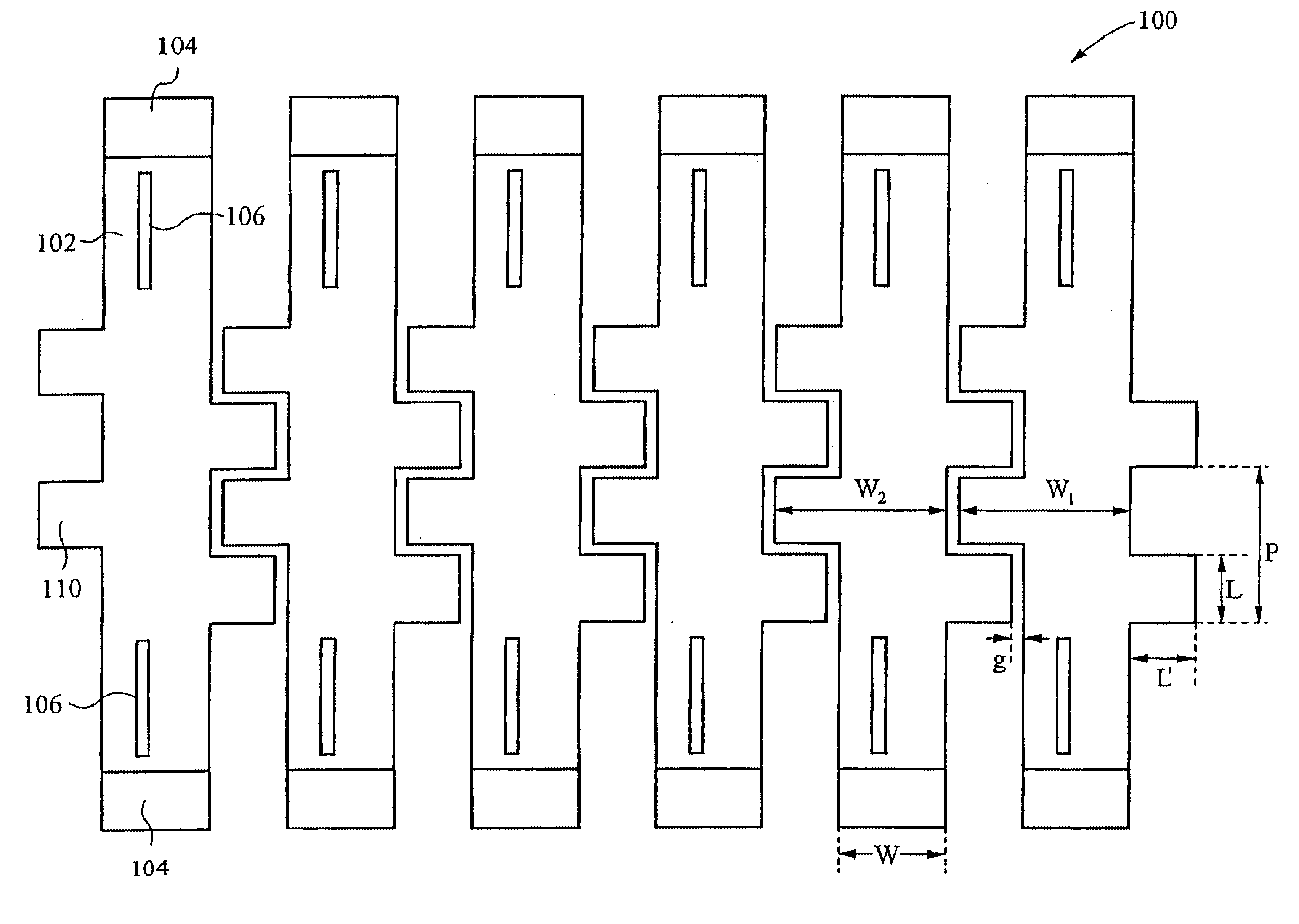
[0024]The present invention overcomes deficiencies of conventional approaches by performing non-linear ribbon cuts at the edges of the ribbons within a diffractive light modulator, thereby providing ribbons with non-linear sides. The non-linear sides substantially reduce the PDL for reflection and diffraction from such ribbons in response to random input polarization states. Preferably, the non-linear sides form a recurring pattern. More preferably, the recurring pattern is formed by alternating halves of a circle. Alternatively, the recurring pattern is formed by alternating a sector of a circle and the mirror image of the sector, by alternating halves of a polygon, for example a square, rectangle or triangle, by a sinusoid, or by a zigzag. Alternatively, the non-linear sides include one or more projections. The projections can form a recurring pattern or the projections can be random. Preferably, each projection or recurring pattern is consistent through the thickness of the ribbo...


PUM


Abstract

A modulator for modulating an incident beam of light. The modulator includes a plurality of elements, each element including a first end, a second end, a first non-linear side, a second non-linear side, and a light reflective planar surface. The light reflective planar surfaces of the plurality of elements lie in one or more parallel planes. The elements are preferably arranged parallel to each other. The modulator also includes a support structure to maintain a position of each element relative to each other and to enable movement of selective ones of the plurality of elements in a direction normal to the one or more parallel planes of the plurality of elements. The plurality of elements are preferably moved between a first modulator configuration wherein the plurality of elements act to reflect the incident beam of light as a plane mirror, and a second modulator configuration wherein the plurality of elements act to diffract the incident beam of light. The non-linear sides substantially reduce the polarization dependent losses for diffraction from the plurality of elements.

Description

FIELD OF THE INVENTION[0001]The present invention relates to an apparatus for mitigating the effects of Polarization Dependent Losses (PDL). More particularly, this invention relates to a structure for PDL mitigation for diffractive MEMS and gratings.BACKGROUND OF THE INVENTION[0002]Designers and inventors have sought to develop a light modulator which can operate alone or together with other modulators. Such modulators should provide high operating speeds (KHz frame rates), a high contrast ratio or modulation depth, have optical flatness, be compatible with VLSI processing techniques, be easy to handle and be relatively low in cost. Two such related systems are found in U.S. Pat. Nos. 5,311,360 and 5,841,579 which are hereby incorporated by reference.[0003]According to the teachings of the '360 and '579 patents, a diffractive light modulator is formed of a multiple mirrored-ribbon structure. An example of such a diffractive light modulator 10 is shown in FIG. 1. The diffractive lig...

Claims


Application Information

Patent Timeline
Patent Type & Authority Patents(United States)
IPC IPC(8): G02B26/08
CPCG02B26/0808
Inventor MAHESHWARI, DINESHDUEWEKE, MICHAEL
Owner SILICON LIGHT MACHINES CORP
Why Eureka
Try Eureka