
Urine dispersing urinal insert device

Inactive Publication Date: 2005-07-26
SUSKI MICHAEL R +1
View PDF18 Cites 54 Cited by
  • Summary
  • Abstract
  • Description
  • Claims
  • Application Information

AI Technical Summary

Benefits of technology

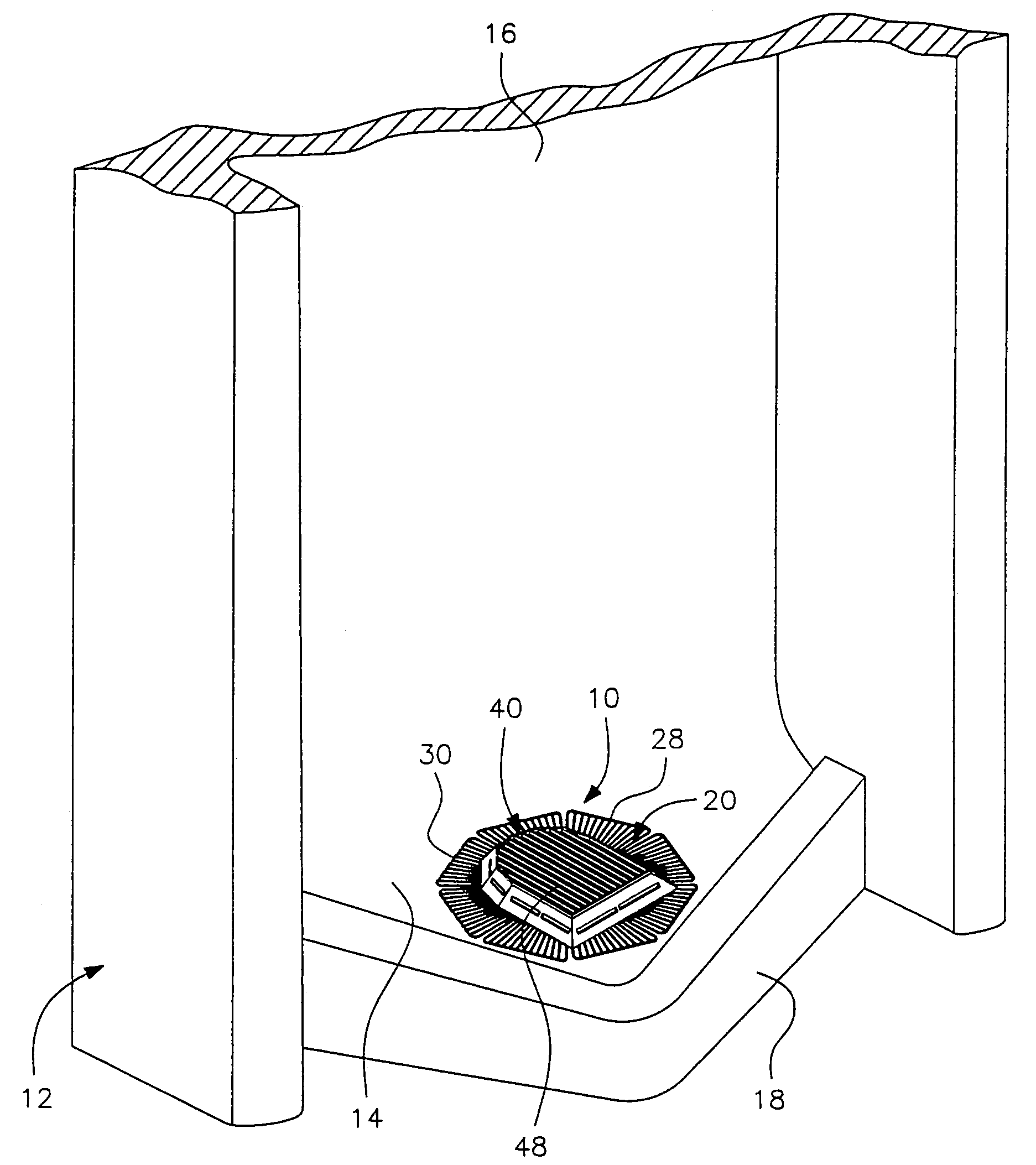
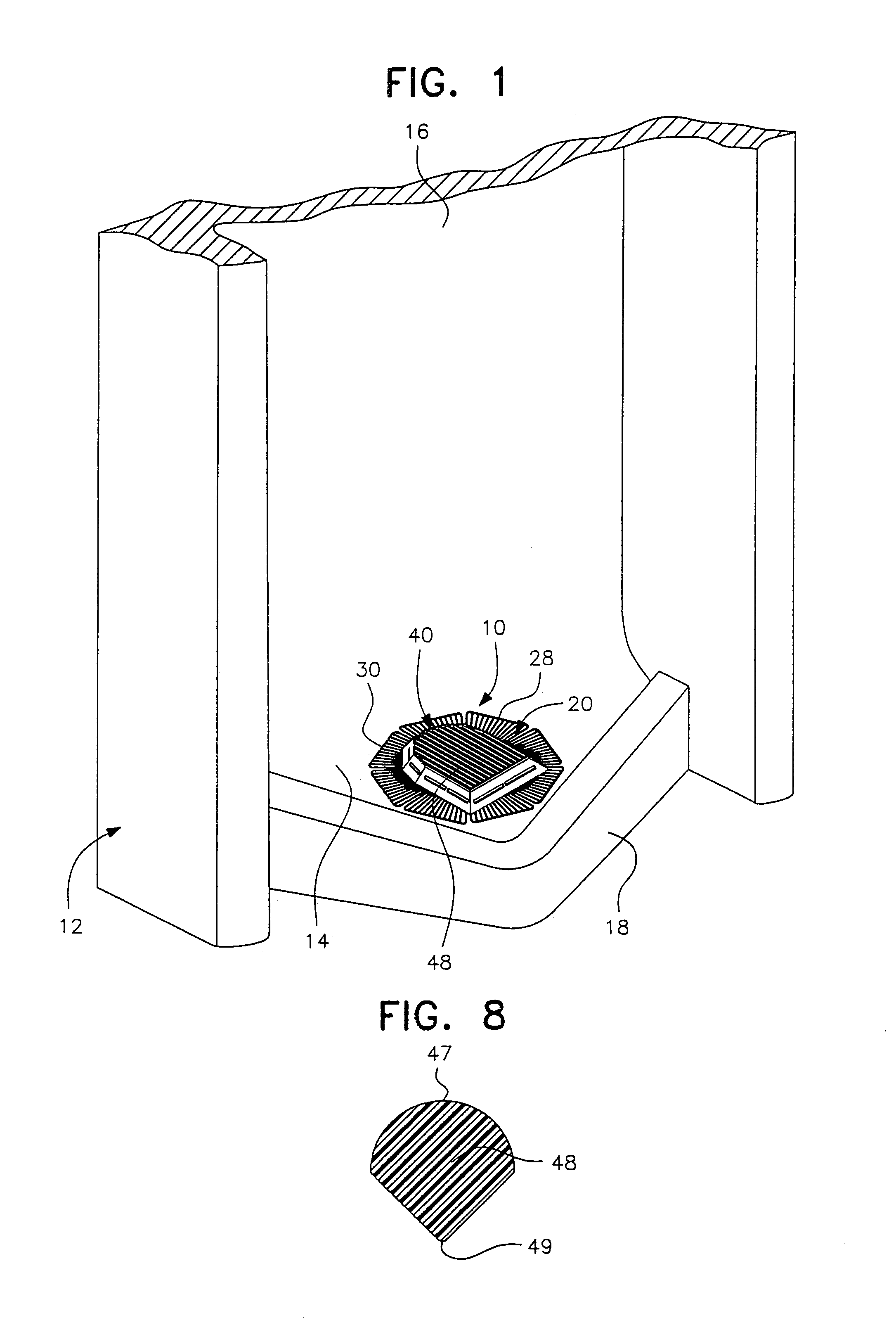
[0006]The disposable, deodorant and splash proof urinal dispersing device of the present invention comprises a framework made of scented plastic material or materials containing at least one type of scent additive. The framework includes a horizontal segmented supporting base with an opening aligned with an outlet opening or a drain in a urinal and a central raised housing. The supporting base has a plurality of perforated segments and a central frame defining the central opening which is surrounded by the segments. The central raised housing has a perforated top member and an upstanding peripheral wall connecting the top member with the central frame in the supporting base. The peripheral wall of the housing includes at least one flush relief opening and is preferably tapered for easy unit stacking. The top member includes a top frame having a plurality of spaced parallel rods which define continuous openings extending from front to rear of the housing and generally in the path of movement of urine being discharged into the urinal. This structure provides a maximum open urine target area for dispersing urine flow without splashing back towards a user of the urinal.
[0007]The supporting base is segmented, which is not disclosed or used in conventional urinal block holders or dispersing devices. The segmented supporting base provides more flexibility and resilience for the urinal dispersing device to adapt to urinals of different sizes and designs. In particular, the supporting base can adjust to urinals with different shapes of bottom designs. In addition, the segmented supporting base is perforated and preferably includes a plurality of openings formed by rod members extending radially outwardly from the central frame. These rod members are progressively tapered toward the distal ends thereof. The tapered supporting rod members provide additional flexibility to the base for adapting to urinals of different sizes and designs. Moreover, the rod members preferably have a notch or notches in their bottom surfaces near the proximal ends to provide further flexibility to the supporting base. For example, the rod members are able to bend upward further than rod members without the notches on tapered configuration to enable the supporting base to fit and conform with, and supportingly engage, urinals of different sizes and designs, for example, a urinal with a deep curved bottom configuration.
[0008]The central raised housing includes a perforated top member, which can be horizontal or inclined. The top member preferably has an arch shape. The peripheral wall connecting the top member with the supporting base can be vertical or inwardly inclined from the supporting base to the top member. An inwardly inclined peripheral wall is preferred because such shape permits the urinal dispersing device of the present invention to stack one on another in a nested overlap relation, thus taking less space, using less resources and easier for packaging, storage and transportation. In addition, urinal dispersing devices are usually sold in six units as one package. Such shape is also convenient for taking orders and sales in a business operation. The peripheral wall also includes openings for the release of urine entered from the top of central raised housing. The top member preferably has rods serving as dispersing filters. The rods preferably include a partial cylindrical or convexly curved upper surface and a V-shape lower surface defining a narrow edge to facilitate dispersing of the urine flow and reduce capillary action along the surface of the rods.

Problems solved by technology

When the deodorant scent additive has dissipated from the dispersing device during use, the device is simply thrown away.
Because the urinal dispersing device is disposable, a longer deodorant life saves resources.

Method used


Image

  • Urine dispersing urinal insert device
  • Urine dispersing urinal insert device
  • Urine dispersing urinal insert device

Examples


Embodiment Construction

[0029]Although only one preferred embodiment of the invention is explained in detail, it is to be understood that the invention is not limited in its scope to the details of construction and arrangement of components set forth in the following description or illustrated in the drawings. The invention is capable of other embodiments and of being practiced or carried out in various ways. Also, in describing the preferred embodiment, specific terminology will be resorted to for the sake of clarity. It is to be understood that each specific term includes all technical equivalents which operate in a similar manner to accomplish a similar purpose.

[0030]FIG. 1 of the drawings illustrates one embodiment of the urine dispersing device of the present invention, generally designated by reference numeral 10. The dispersing device 10 is installed in a conventional urinal, generally designated by reference numeral 12, provided with an outlet or drain (not shown) in the curved bottom wall 14 which...


PUM


Abstract

A disposable, deodorant and splash proof urine dispersing device for placement in a urinal including a framework made of scented plastic material with a horizontal segmented supporting base and a central raised housing. The supporting base includes a plurality of perforated flexible segments and a central bottom frame with a central opening aligned with an outlet or drain in the urinal. The opening is surrounded by the multiple segments such that the device can flex and adapt to urinals of different sizes and designs. The central raised housing includes a horizontal or inclined top member and an upstanding peripheral wall connecting the top member with the central bottom frame in the supporting base. The peripheral wall includes flush relief openings and tapered for easy unit stacking. The top member includes a frame with a plurality of spaced parallel rods having a unique configuration for dispersing urine flow with reduced back splashing toward the user of the urinal.

Description

BACKGROUND OF THE INVENTION[0001]1. Field of the Invention[0002]The present invention relates generally to a urine dispersing urinal insert and, more particularly, to a disposable, deodorant and splash proof urine dispersing device which is made of a scent impregnated plastic material or materials for deodorization purposes with a central raised housing and a segmented flexible supporting base for adapting to urinals of various sizes and designs.[0003]2. Description of the Prior Art[0004]Deodorant block holders are commercially available and generally include a flexible pad with a perforate receptacle on the upper surface of the pad for receiving a deodorant block which must be periodically replaced. The replacement of the deodorant block is somewhat difficult. The construction of some presently available commercial devices utilize upwardly facing flat surfaces which cause splashing of urine when urine flow impacts against the flat surfaces. Some splash-proof inserts have been devel...

Claims


Application Information

Patent Timeline
IPC IPC(8): A47C19/00E03D13/00
CPCE03D13/00E03D13/005Y10S4/05
Inventor SUSKI, MICHAEL R.SUSKI, MICHAEL F.
Owner SUSKI MICHAEL R
Learn More