
Electric wrench for vehicle repairing

a technology for electric wrenches and vehicles, applied in the direction of manufacturing tools, percussive tools, portable drilling machines, etc., can solve the problems of high manufacturing cost, time-consuming and laborious, complex structure, etc., and achieve high output torque, simple construction, and high output torque

Inactive Publication Date: 2005-07-19
WING WIDE HK
View PDF5 Cites 2 Cited by
  • Summary
  • Abstract
  • Description
  • Claims
  • Application Information

AI Technical Summary

Benefits of technology

[0003]In view of the aforesaid disadvantages now present in the prior art, the present invention provides an improved power wrench for vehicle repair equipped with a power accumulator controlled by a clutch, which is with simple structure and can generate high output torque without producing reaction torque and angular force.
[0006]The impact surface between the hammer and the hammer block is at an oblique angle in the range of 5° to 15° to facilitate ease of engagement and disengagement.
[0008]It is an object of the present invention is to provide an improved power wrench for vehicle repair, which is of simple construction and can generate high output torque.
[0009]It is another object of the present invention is to provide an improved wrench which can generate high output torque without producing reaction torque and angular force, thus overcoming the disadvantages of the prior art.
[0010]It is a further object of the present invention is to provide a power wrench which is susceptible of a low cost of manufacture with regard to both materials and labor, and which accordingly is then susceptible of low prices of sale to the consuming public.

Problems solved by technology

For a long time, manual wrenches have been used to loosen and tighten the bolts and nuts so as to replace flat tires, and it is time consuming and laborious.
However, some existing power wrenches use compressed air and so their structure is complicated and their manufacturing cost is high.
Some other existing wrenches are with simplified structure but the output torque is not high enough and reaction torque and angular force commonly arise.

Method used


Image

  • Electric wrench for vehicle repairing
  • Electric wrench for vehicle repairing
  • Electric wrench for vehicle repairing

Examples


Embodiment Construction

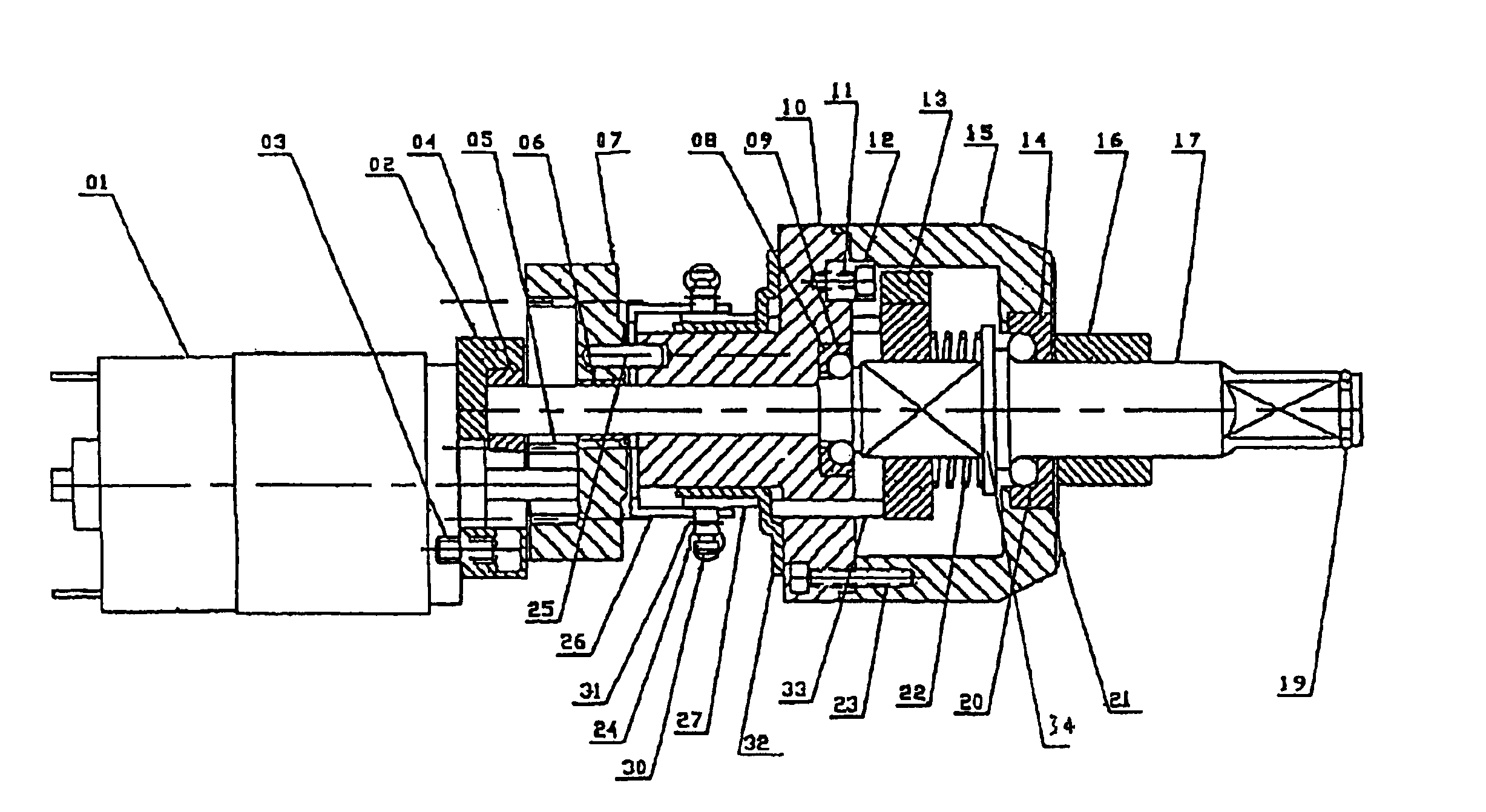
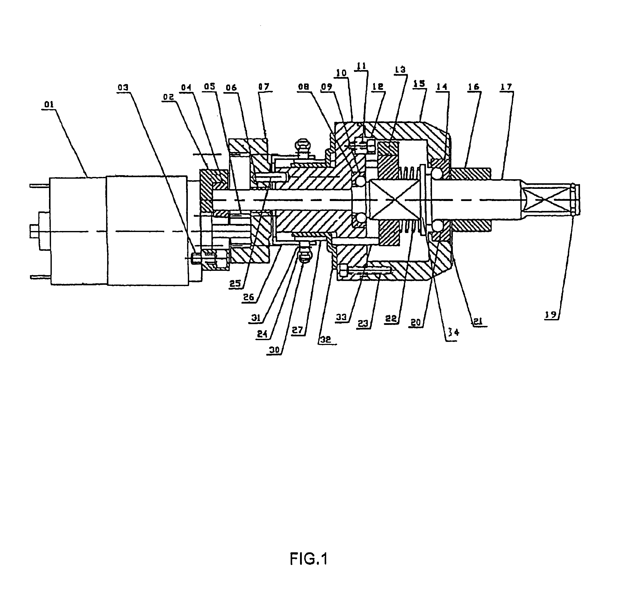
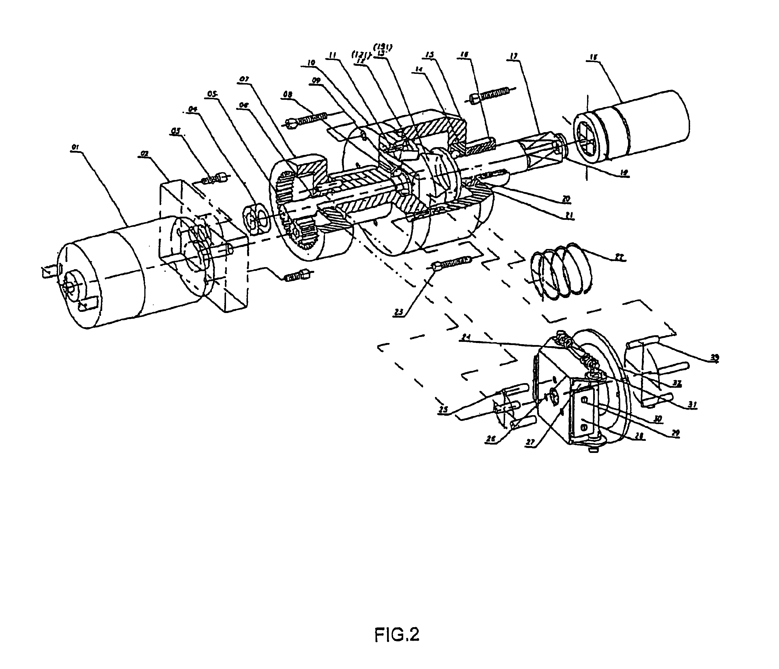
[0019]As illustrated in FIG. 1 and FIG. 2, the electric wrench generally comprises a DC driving motor 01, transmission gears, a clutch, a power accumulator and a transmission shaft 17.

[0020]The DC driving motor 01 is connected to the power source at one end with power supply from a motor vehicle's battery and the other end of which is fixed onto a motor bracket 02 by at least one screw 03 with a slot on the motor bracket 02 above the center axis for placing one end of a transmission shaft 17 and the center of which is connected to a motor gear 05 through the motor bracket 02.

[0021]The transmission gears include a wheel gear 07 with a hole in the center for the transmission shaft 17 to go through and with the motor gear 05 inside it below the hole and the gear teeth of the motor gear 05 and the wheel gear 07 meshing with one another.

[0022]The clutch has a hole in the center for the transmission shaft 17 to go through and a clutch bracket 26 with at least one hole for fixing the clutc...


PUM

PropertyMeasurementUnit
Angleaaaaaaaaaa
Angleaaaaaaaaaa
Angleaaaaaaaaaa

Abstract

The present invention relates to an electric wrench for vehicle repairing which comprises a DC driving motor, transmission gears, a clutch, a power accumulator and a transmission shaft. When the DC driving motor rotates, it will drive the transmission gears which will in turn drive the power accumulator to rotate with high speed. The power accumulator will drive the clutch to rotate. When the power accumulator reaches the pre-set high speed, it accumulates sufficient inertial force. Owing to centrifugal force, the clutch will make a hammer block to impact a hammer inside the power accumulator, thus driving the transmission shaft to rotate suddenly. The electric wrench is with simple structure and can generate high output torque without producing reaction torque and angular force.

Description

BACKGROUND OF THE INVENTION[0001]The present invention relates to an electric wrench for vehicle repair and more particularly pertains to an electric wrench carried along in a motor vehicle using power supply from the motor vehicle for changing tires by loosening and tightening the bolts and nuts that fasten the wheels of the motor vehicle or of other motor vehicles.[0002]It is not uncommon for a driver to replace a flat tire urgently on a highway or at place where there is not a car repair shop nearby or when it is not possible to call for emergency car repair service. For a long time, manual wrenches have been used to loosen and tighten the bolts and nuts so as to replace flat tires, and it is time consuming and laborious. There are now power wrenches existing in the marketplace for ease of tire replacement. However, some existing power wrenches use compressed air and so their structure is complicated and their manufacturing cost is high. Some other existing wrenches are with simp...

Claims


Application Information

Patent Timeline
IPC IPC(8): B25B21/02
CPCB25B21/02B25B21/026
Inventor CHAN, IN FONG
Owner WING WIDE HK
Learn More