Raised access floor system

Inactive Publication Date: 2005-07-19
HAWORTH SPA
View PDF43 Cites 83 Cited by
  • Summary
  • Abstract
  • Description
  • Claims
  • Application Information

AI Technical Summary

Benefits of technology

[0011]It is also an object of this invention to provide an improved cable management arrangement for use in association with a raised floor system, which cable management system employs a basic cable manager formed generally in one piece and having connecting parts integrally associated therewith, the latter preferably being resiliently deflectable to permit them to be easily engaged with adjacent pedestals without requiring separate mounting parts or hardware, whereby the cable management devices can be readily installed with the raised floor system in a simple and economical manner, thereby overcoming or at least minimizing many of the disadvantages associated with prior systems as discussed above.
[0012]The present invention relates to an improved steel and concrete composite floor panel intended for use in a raised floor system, wherein the floor panel is defined by a thin metal (i.e. steel) pan which defines a shallow upwardly opening compartment therein which is filled with concrete. The horizontally large bottom wall of the pan has a significantly large center portion which is deformed upwardly relative to the edge portions so that the center portion of the concrete will be of reduced thickness relative to the edge portion of the concrete, the latter cooperating with side walls on the pan and being confined between the bottom wall and the top flange so that the edges of the floor panel have a high strength beamlike structure extending therealong, whereas the reduced center thickness of the concrete permits reduction in floor panel weight while permitting more efficient utilization of the strength properties of the panel. The bottom wall also has a first plurality of projections protruding upwardly therefrom which create a mechanical interlock with the concrete. The bottom wall of the pan also has a plurality of second projections protruding upwardly therefrom into the concrete, the second projections being smaller and of significantly greater numbers than the first projections so as to provide supportive engagement with the concrete at a large number of locations so that the loading stresses imposed on the concrete, and specifically the tension stresses thereon adjacent the bottom of the concrete, are immediately transferred to the bottom wall of the steel pan at a large number of locations so as to minimize the tendency for the concrete to fail under tension.
[0013]The improved floor panel of the present invention, as aforesaid, also has a gusseted corner associated with the metal pan so as to improve the strength and rigidity thereof, with the gusseted corner defining therein a step or shoulder positioned downwardly from the upper corner of the top flange so that the corner of the pan, when seated on a pedestal head, can be at least partially supportingly engaged at the step to provide for improved supportive engagement with the pedestal.
[0016]The pedestal assembly of the present invention in addition includes improved connecting features integrally associated therewith, such as with the base of the pedestal, for facilitating attachment of one half of a clamp, the other half of the clamp being integrated on the base, to permit a grounding wire to be easily and efficiently coupled to the pedestal.

Problems solved by technology

In known floors employing composite steel and concrete floor panels, many of the floor panels have a substantially uniform depth throughout the pan such that the quantity of concrete utilized and the resulting weight of the floor panel is heavy.
These arrangements also result in the bottom of the concrete being loaded in tension when the upper surface of the floor panel is subjected to heavy loads, and since concrete does not possess good durability when loaded in tension, it has been observed that floor panels of this type undergo undesired cracking and failure.
These projections often are lanced upwardly from the bottom wall of the pan, thereby leaving openings in the bottom of the pan whereby filling of the pan with wet concrete creates leakage or seal problems which hence complicate the overall manufacturing process.
The overall largeness of this open space makes organization and identification of the various cables difficult.
While these devices, which typically are formed as large upwardly opening trays or the like, have been at least partially effective with respect to being able to organize and identify the plurality of cables, nevertheless the devices are for the most part bulky and must be purchased from a separate supplier and effectively interfitted into the space below the raised floor, such that the overall purchase and installation of the raised floor becomes more complex and expensive.
This is a time consuming and adaptive effort since the electrician must identify and provide clamps which can be suitably secured to the pedestal.
This hence increases the overall structural complexity and cost of such devices, and in particular makes installation of such devices more difficult and time-consuming.
Further, some of these devices require that special runners be provided for supporting the floor panel in order to also accommodate the cable support device, and this hence significantly increases the overall complexity and cost of the system.

Method used


Image

  • Raised access floor system
  • Raised access floor system
  • Raised access floor system

Examples


Embodiment Construction

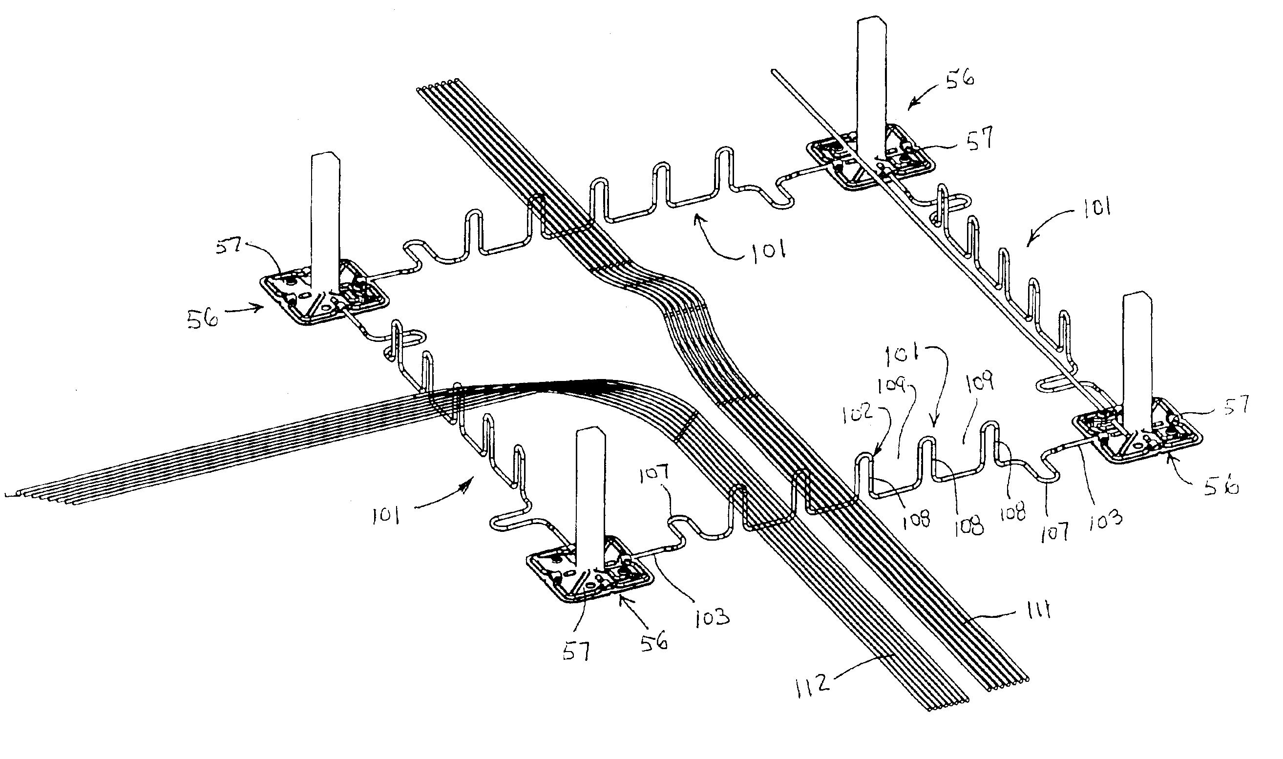
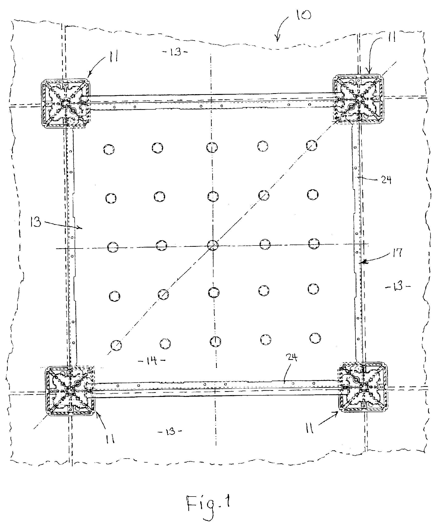
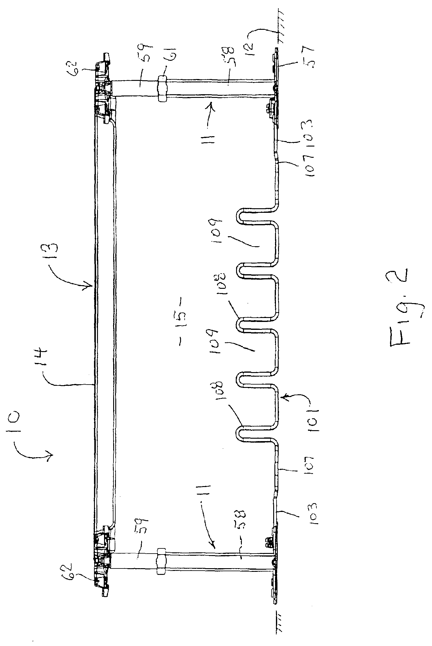
[0056]Referring to FIGS. 1 and 2, there is illustrated a raised access floor system according to the present invention. The system 10, as is generally conventional, includes a plurality of height-adjustable upright pedestals 11 which are supported on and project upwardly from a base surface 12, such as a conventional building floor, with the pedestals being arranged in aligned transversely-extending rows and columns to define a square grid. A plurality of removable floor panels or tiles 13 are supported on the upper ends of the pedestals, which floor panels are typically square and supported on the pedestals in such a manner that each floor panel has the four corners thereof supported on a separate pedestal, with each pedestal typically in turn supporting thereon the corners of four adjacent floor panels. The upper surfaces 14 of the floor panels may directly define the floor, or alternatively the surfaces may have a suitable floor covering such as carpet tiles disposed thereover. T...


PUM


Abstract

A floor panel for a raised access floor system, including a shallow metal pan with a bottom wall and a shallow upwardly-opening compartment. The bottom wall has a plurality of first hollow projections projecting upwardly therefrom, which projections adjacent upper ends thereof having sidewardly projecting rib structure. The bottom wall also has a plurality of microfeatures which project upwardly through a lesser extent. The number of microfeatures is substantially greater than the number of projections. The pan side walls and bottom wall are free of openings therethrough. A mass of solidified concrete fills the compartment. The floor panel is supported on a pedestal having a base which has clamping and mounting features integrated thereon for engaging grounding wires and cable management members.

Description

CROSS-REFERENCE TO RELATED APPLICATION[0001]This application claims priority under 35 USC §119(e) of copending provisional application Ser. No. 60 / 359,356 filed Feb. 25, 2002, the entire disclosure of which is herein incorporated by reference.FIELD OF THE INVENTION[0002]This invention relates to a raised access floor assembly and, more specifically, to a system utilizing improved steel and concrete composite floor panels.[0003]The invention also relates to an improved raised access floor system incorporating improved pedestals for supporting the floor panels, and specifically pedestals which have improved supportive engagement with the floor panels and which additionally have integrated features for accommodating grounding wires and cable management members.BACKGROUND OF THE INVENTION[0004]A significant variety of raised access floor systems have been developed for use in commercial buildings. Such systems typically employ a plurality of height-adjustable pedestals which are support...

Claims


Application Information

Patent Timeline
IPC IPC(8): E04F15/024E04B5/48E04B5/00
CPCE04B5/48E04F15/024E04F15/02429E04F15/02452H02G3/285
Inventor JAKOB-BAMBERG, RUPERTMARSHALL, DALELONG, DARRENCLINTBERG, JAYSHIVAK, VINCENTSPAVOR, PAUL
Owner HAWORTH SPA
Why Eureka
Try Eureka